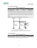
35
Model FL4000H
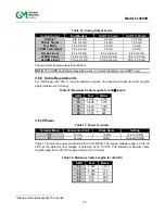
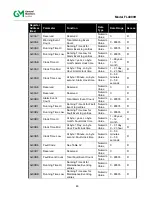
Table 15: Analog Output Levels
Analog Output
Dual Modbus
HART (3.5 mA)
HART (1.25 mA)
Startup
8
0 to 0.2 mA
3.5 mA
1.25 mA
FAULT Signal
0 to 0.2 mA
3.5 mA
1.25 mA
Test Mode
1.5 ± 0.2 mA
3.5 mA
1.5 mA
COPM Fault Signal
2.0 ± 0.2 mA
3.5 mA
2.0 mA
Ready signal
4.3 ± 0.2 mA
4.3 ± 0.2 mA
4.3 ± 0.2 mA
WARN signal
16.0 ± 0.2 mA
16.0 ± 0.2 mA
16.0 ± 0.2 mA
ALARM signal
20.0 ± 0.2 mA
20.0 ± 0.2 mA
20.0 ± 0.2 mA
The maximum analog output load is 600
.
NOTE:
The COPM Fault Signal may also be set to 0 mA at the factory (non HART only).
3.6.9 Cable
Requirements
For interfacing with 250
input impedance devices, the following maximum cable lengths
apply (maximum 50
loop):
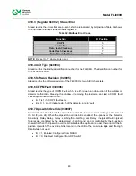
Table 16: Maximum Cable Lengths for 250
Inputs
AWG
Feet
Meters
14
9,000 2,750
16
5,800 1,770
18
3,800 1,160
20
2,400 730
22
1,700 520
3.6.10 Power
Table 17: Power Terminals
Terminal Block
Connection Point
Block Name
Setting
P1
Term 8
+24IN
+24 V
In
(VDC)
P1
Term 9
GND
Ground (COM)
Table 17 shows the power connections for the FL4000H. The supply voltage range is 20 to 36
VDC at the detector (low voltage is detected at 18.5 VDC). The following maximum cable
lengths apply for a +24 VDC supply (maximum 20
loop):
Table 18: Maximum Cable Lengths for +24 VDC
AWG
Feet
Meters
14
4,500 1,370
16
2,340 715
18
1,540 470
20
970 300
22
670 205
8
Startup mode lasts exactly 15 seconds.
Содержание FL4000H
Страница 2: ...ii Model FL4000H This page intentionally left blank ...
Страница 8: ...viii Model FL4000H Figure 2 Mounting Instruction Figure 3 Wall Mounting Assembly ...
Страница 28: ...28 Model FL4000H Figure 16 Detector Mounting and Installation ...
Страница 61: ...61 Model FL4000H 6 2 Final Assembly Figure 26 FL4000H Cross Section View ...

