48
Model FL4000H
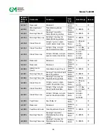
4.10.3 (Register 0x0002) Status/Error
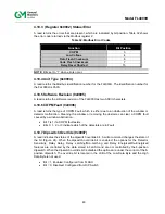
A read returns the errors that are present, which are indicated by bit position. Table 32 shows
the error code returned via the Modbus register 2:
Table 32: Modbus Error Codes
Function
Bit Position
COPM
3
Low Voltage
4
Data Flash Checksum
6
Code Flash Checksum
7
Relay Reset Shorted
15
NOTE
: Bits set to “1” when errors occur.
4.10.4 Unit Type (0x0004)
A read returns the Modbus identification number for the FL4000H. The identification number for
the FL4000H is 3500.
4.10.5 Software Revision (0x0005)
A read returns the software revision of the FL4000H as two ASCII characters.
4.10.6 COPM Fault (0x0006)
A read returns the type of COPM Fault, which is either due to an obstruction of the window or
detector malfunction. Cleaning the window or removing the obstacle can clear a COPM fault
caused by a window obstruction.
Bit 7 is 1 if a COPM fault exists
Bits 0, 1, 2, or 3 indicate which of the detectors are in Fault
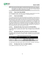
4.10.7 Dipswitch Override (0x0007)
A read indicates the status of the dipswitch override bit. A write command changes the state of
the bit (Figure 24). When the dipswitch override bit is enabled, the options for the Detector
Sensitivity, Relay Delay, Relay Latching/Non-Latching and Relay Energized/De-Energized
features are controlled by the data stored in FLASH and are not controlled by the 8-position
dipswitch. When the dipswitch override bit is disabled the options are under the control of the 8-
position dipswitch. The override bit is located in the LSB of the Low Data Byte and the High
Data Byte is not used.
Bit = 1, Enabled: Configured from FLASH
Bit = 0, Disabled: Configured from DIP Switch
Содержание FL4000H
Страница 2: ...ii Model FL4000H This page intentionally left blank ...
Страница 8: ...viii Model FL4000H Figure 2 Mounting Instruction Figure 3 Wall Mounting Assembly ...
Страница 28: ...28 Model FL4000H Figure 16 Detector Mounting and Installation ...
Страница 61: ...61 Model FL4000H 6 2 Final Assembly Figure 26 FL4000H Cross Section View ...

