52
Model FL4000H
4.10.23
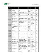
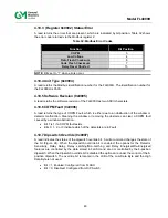
COM1 and COM2 Function Code Errors (0x0022)
A read indicates the total Modbus COM1 & COM2 function code errors that occurred in the
slave device. The maximum count is 65535, after which the counter resets to zero and begins
counting anew.
4.10.24 Starting
Register
Address Errors (0x0023)
A read indicates the number of starting register address errors. The maximum count is 65535,
after which the counter resets to zero and begins counting anew.
4.10.25
Total Receive Errors – COM1 only (0x0024)
A read indicates the total number of Modbus COM1 receive errors in the FL4000H. The
maximum count is 65535, after which the counter resets to zero and begins counting anew.
4.10.26
CRC Errors Low – COM1 and COM2 (0x0025)
A read indicates the total number of COM1 or COM2 CRC low byte errors in the FL4000H. The
maximum count is 65535, after which the counter resets to zero and begins counting anew.
4.10.27
CRC Errors Hi – COM1 and COM2 (0x0026)
A read indicates the number of COM1 and COM2 CRC Hi byte errors that occurred in the
FL4000H. The maximum count is 65535, after which the counter resets to zero and begins
counting anew.
4.10.28
Total Overrun Errors – COM1 only (0x0027)
A read indicates the number of COM1 Overrun Errors that occurred in the FL4000H. The
maximum count is 65535, after which the counter resets to zero and begins counting anew.
NOTE:
An overrun error occurs when a subsequent received data byte overwrites an earlier
unprocessed data byte. As a result, one of the received data bytes will be corrupted.
4.10.29
Total Framing Errors – COM1 and COM2 (0x0029)
A read indicates the number of Comm 1 and Comm 2 Framing Errors that occurred in the
FL4000H. The maximum count is 65535, after which the counter resets to zero and begins
counting anew.
4.10.30
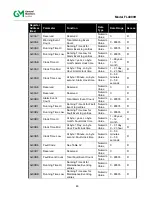
Clear Communication Errors (0x002D)
A read indicates the total number of Modbus communication errors. The maximum count is
65535, after which the counter resets to zero and begins counting anew. A write resets this
value to 0. Only a write of value “0” is allowed for this register.
4.10.31
Enable/disable small HART current (0x002E)
Normally in HART mode the analog output current does not go below 3.5 mA and register 0x2E
reads 0. If a value of 1 is written to the register 0x2E, the minimum HART current becomes
1.25 mA. This allows to distinguish several operating modes that have output current below 3.5
mA.
4.10.32
COM2 Address (0x002F)
A read returns the COM2 address of the FL4000H. A write changes the address to the
requested number. The range of the address is from 1 to 247 (01 to F7 in Hex). After changing
the address of the FL4000H, it will be necessary for the controlling or master device to similarly
Содержание FL4000H
Страница 2: ...ii Model FL4000H This page intentionally left blank ...
Страница 8: ...viii Model FL4000H Figure 2 Mounting Instruction Figure 3 Wall Mounting Assembly ...
Страница 28: ...28 Model FL4000H Figure 16 Detector Mounting and Installation ...
Страница 61: ...61 Model FL4000H 6 2 Final Assembly Figure 26 FL4000H Cross Section View ...

