50
Model FL4000H
NOTE:
If the address is not in range an Illegal Data Value (03) is returned. By grounding the
RESET input during the first 1 second of the power up cycle, the FL4000H Address will
default to 1. The address will be set to a default of 1 when the red and green LED’s
flash alternately after approximately 1 second, at which time the RESET input can be
released from ground.
4.10.10
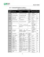
COM1 Baud Rate (0x000B)
A read command returns the current baud rate for COM1 channel. A write command changes
the baud rate to the requested values. Valid settings are shown in Table 33.
Factory default is
19,200 baud.
Table 33: Com1 Baud Rate
Baud Rate
Value
Access
2,400
0
Read / Write
4,800
1
Read / Write
9,600
2
Read / Write
19,200
3
Read / Write
38,400
4
Read / Write
NOTE:
If the baud rate is not in range, an Illegal Data Value (03) is returned. By grounding the
RESET input during the first 1 second of the power up cycle, the FL4000H Baud Rate
will default to 19.2K. The baud rate will be set to a default of 19.2K when the red and
green LED’s flash alternately after approximately 1 second, at which time the RESET
input can be released from ground.
4.10.11
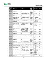
COM1 Data Format (0x000C)
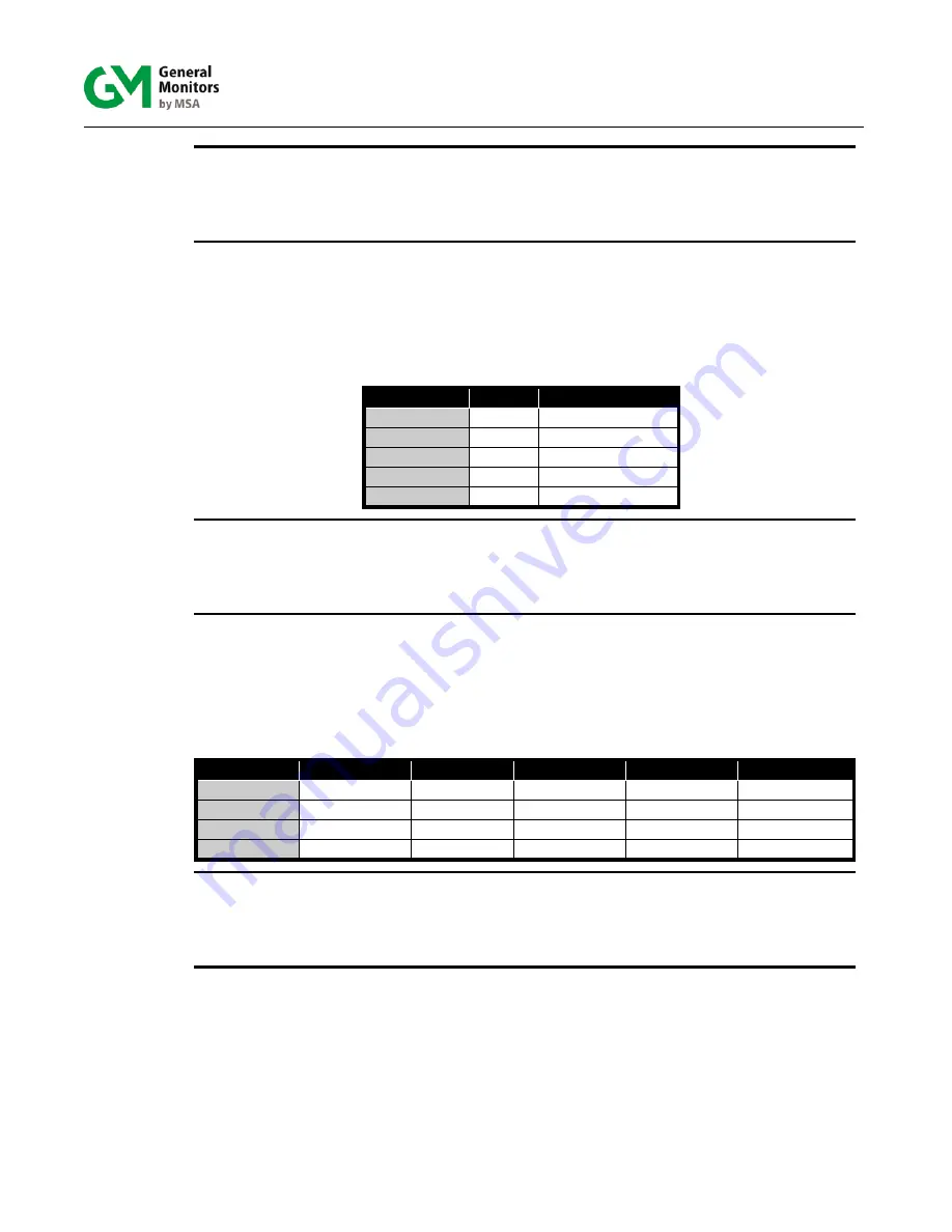
A read command returns the current data format for COM1 channel. Write command changes
the data format to the requested values. Valid settings are shown in Table 34. Default format is
8-N-1.
Table 34: Selectable Data Formats
Format
Parity
Stop
Data Bits
Value
Access
8-N-1
None
1
8
0
Read / Write
8-E-1
Even
1
8
1
Read / Write
8-O-1
Odd
1
8
2
Read / Write
8-N-2
None
2
8
3
Read / Write
NOTE:
If the data format is not in range, an Illegal Data Value (03) is returned. By grounding
the RESET input during the first 1 second of the power up cycle, the FL4000H Data
Format will default to 8-N-1. The Data Format will be set to a default of 8-N-1 when the
red and green LED’s flash alternately after approximately 1 second, at which time the
RESET input can be released from ground.
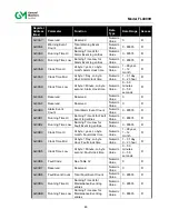
4.10.12 COPM
Counts
Sensor 1 (0x000D)
A read indicates the number of COPM Faults that have occurred for sensor 1 in the FL4000H.
Please refer to Section 2.4.2 for more information on COPM and Section 6.0 for
troubleshooting tips.
Содержание FL4000H
Страница 2: ...ii Model FL4000H This page intentionally left blank ...
Страница 8: ...viii Model FL4000H Figure 2 Mounting Instruction Figure 3 Wall Mounting Assembly ...
Страница 28: ...28 Model FL4000H Figure 16 Detector Mounting and Installation ...
Страница 61: ...61 Model FL4000H 6 2 Final Assembly Figure 26 FL4000H Cross Section View ...

