32
Model FL4000H
3.6.2 Warning
Relay
Table 9: Warning Relay Terminals
Terminal Block
Connection
Point
Block Name
User Relay Settings
Normally De-
energized
Normally
Energized
P2
Term 8
WARNC
Warn Common
Warn Common
P2
Term 9
WARN1
Warn NC
Warn NO
P2
Term 10
WARN2
Warn NO
Warn NC
NOTE
: NO = Normally Open; NC = Normally Closed
Description: These connections are to the SPDT WARN relay. The WARN output is immediate
on the FL4000H. The WARN output can be normally energized or de-energized, latching, or
non-latching. These options are also set via Modbus or by a dipswitch (Section 3.7 ). The
WARN relay contact ratings are 8 A @ 250 VAC and 8 A @ 30 VDC.
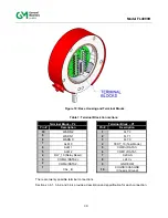
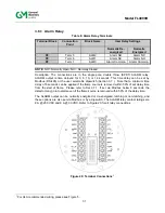
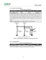
Refer to Figure 20 for all relay connections.
3.6.3 Alarm
Wiring
Relay Protection
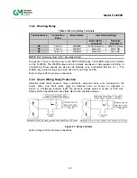
Inductive loads (bells, buzzers, relay, contractors, solenoid valves, etc.) connected to the
Alarm, Warn, and Fault relays must be clamped down as shown on diagrams in
Figure 21. Unclamped inductive loads can generate voltage spikes in excess of 1000 volts.
Spikes of this magnitude will cause false alarms and possible damage.
Figure 21: Relay Contacts
Refer to Figure 20 for all relay connections.
Содержание FL4000H
Страница 2: ...ii Model FL4000H This page intentionally left blank ...
Страница 8: ...viii Model FL4000H Figure 2 Mounting Instruction Figure 3 Wall Mounting Assembly ...
Страница 28: ...28 Model FL4000H Figure 16 Detector Mounting and Installation ...
Страница 61: ...61 Model FL4000H 6 2 Final Assembly Figure 26 FL4000H Cross Section View ...

