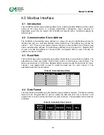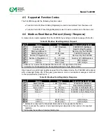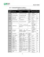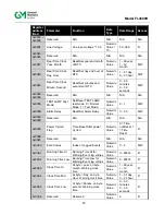
42
Model FL4000H
order to prevent this condition from occurring; the maximum response time for the
FL4000H is 200 milliseconds. Therefore, the master’s timeout setting should be set to
200 milliseconds or greater.
If the FL4000H receives the query without a communications error, but cannot process
it due to reading or writing to a non-existent FL4000H command register, then the
FL4000H returns an exception response message informing the master of the error.
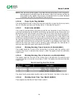
The exception response message has two fields that differentiate it from a normal response.
The first is the function code – byte 2. This code will be 0x83 for a read exception and 0x86 for
a write exception. The second differentiating field is the exception code – byte 3 (Section 4.8.2).
In addition, the total exception response length is 5-bytes rather than the normal message
length.
Table 28: Exception Response
Byte
Modbus
Range
Referenced to FL4000H
1
st
Slave Address
1-247* (Decimal)
FL4000H ID (Address)
2
nd
Function Code
83 or 86 (Hex)
Preset Single Registers
3
rd
Exception Code 01 – 06 (Hex)
Appropriate Exception Code (See Below)
4
th
CRC Hi
00-FF (Hex)
CRC Hi Byte
5
th
CRC Lo
00-FF (Hex)
CRC Lo Byte
* Address 0 is reserved for Broadcast Mode and is not supported at this time.
4.8.2 Exception
Code
Exception Code Field:
In a normal response, the FL4000H returns data and status in the
response data field. In an exception response, the FL4000H returns an exception code
(describing the FL4000H condition) in the data field. Below is a list of exception codes that are
supported by the FL4000H:
Table 29: Exception Codes
Code
Name
Description
01
Illegal Function
The function code received in the query is not an allowable
action for the FL4000H.
02
Illegal Data Address
The data address received in the query is not an allowable
address for the FL4000H.
03
Illegal Data Value
A value contained in the query data field is not an allowable
value for the FL4000H.
04
Reserved NA
Содержание FL4000H
Страница 2: ...ii Model FL4000H This page intentionally left blank ...
Страница 8: ...viii Model FL4000H Figure 2 Mounting Instruction Figure 3 Wall Mounting Assembly ...
Страница 28: ...28 Model FL4000H Figure 16 Detector Mounting and Installation ...
Страница 61: ...61 Model FL4000H 6 2 Final Assembly Figure 26 FL4000H Cross Section View ...


