ORTHORALIX 9200
Service Manual
B-17
Gendex Dental Systems 4519-190-71193-7
B.5.11
Creating a network connection for the
Orthoralix 9200
B.5.11.1
Orthoralix 9200 DDE/Ceph
Contact an office administrator to determine the static IP
address that should be assigned to the Orthoralix 9200
before the configuration steps are performed.
To create a network connection for the Orthoralix 9200, there
are two options: directly to a PC or through a networking device
(router, hub, switch, etc.). If you will connect the 9200 directly to
a PC, you must use a crossover cable. A 10 m. (32 ft.) crossover
cable is supplied, but a crossover cable that is no longer than 25
m. (82 ft.) can be used. If you will be using a networking device,
an ordinary CAT-5 Ethernet cable is used. A 10 m. (32 ft.) Ethernet
cable is supplied, but an Ethernet cable that is no longer than 25
m. (82 ft.) can be used.
Before you begin these steps, make sure you have a PC set up and
positioned to be used as the workstation that will receive images
from the 9200. This PC must have a working Ethernet Network
Interface Card (NIC) already installed. Perform the following steps
to configure the 9200 network connection:
Connecting directly to a PC (static IP address)
1.
Connect the crossover cable
from the PC’s NIC to the Eth-
ernet port at the base of the
9200 column next to the mains
power switch.
2.
Install the imaging application software on the PC.
3.
Insert the GxPicture CD-ROM into the PC’s CD-ROM drive
and install the ActiveX driver for the Orthoralix 9200. Refer
to the GxPicture Quick Installation Guide for more informa-
tion regarding this software. An icon will appear on your
PC’s desktop that can be used to launch the Configuration
Manager.
4.
Insert the supplied CD-ROM and install the necessary
sensor.dat file. An icon for the Orthoralix 9200 will appear in
the system tray near the clock on your PC’s desktop. This icon
can be used to launch the Orthoralix DDE Setup Screen.
5.
Turn off the Orthoralix 9200.
6.
Press and hold the No Radiation
and Patient Selection
buttons on the 9200 control panel. While holding them, turn
on the power. This will start Service Mode.
7.
Press the Anterior Carriage Movement
button several
times until the IP address appears on the display. If you need
to change the IP address, use the following buttons:
kV Decrease and Increase:
Use these to change the first
set of numbers (ex. XXX.16.137.180
mA Decrease and Increase:
Use these to change the second
set of numbers (ex. 172.XXX.137.180)
s Increase or Decrease:
Use these to change the third set
of numbers (ex. 172.16.XXX.180)
Projection Browsing:
Use these to change the fourth set
of numbers (ex. 172.16.137.XXX)
When you are finished making any changes,press and hold
the No Radiation
button to save the new IP address.
8.
Press the Anterior Carriage Movement
button until the
Subnet Mask is displayed. To change the Subnet Mask, use
the same buttons that were used when changing the IP ad-
dress. When you are finished, press and hold the No Radiation
button to save the new Subnet Mask.
9.
Turn the 9200 off and then on.
10. Click Windows
Start
,
Run
, type
cmd
, and then click
OK
. Type
ipconfig and press Enter. This will display the IP information
of your computer which you will need to know in the next
step.
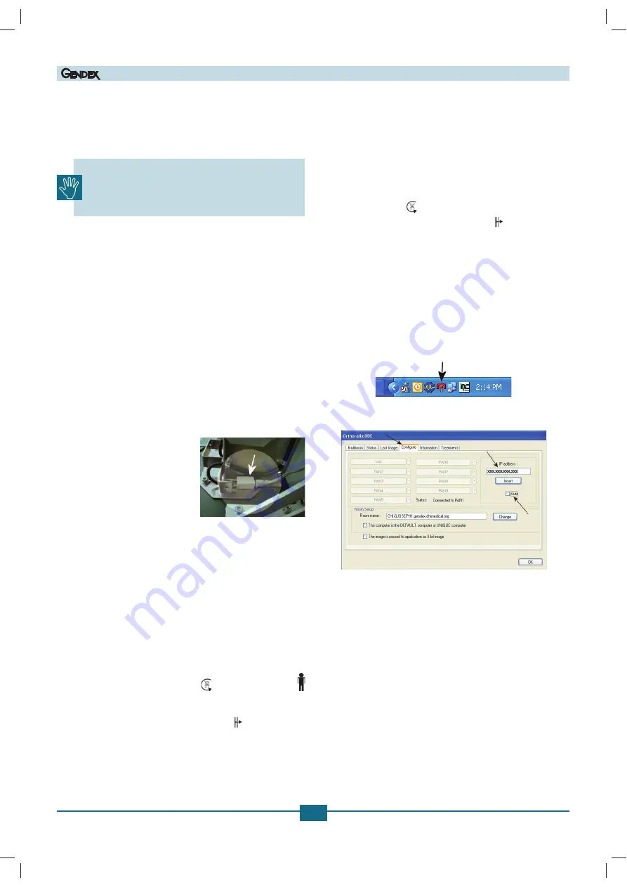
11. Click the DDE Pan icon in the system tray.
12. Click the Configure tab and then deselect Auto.
13. Type the IP address from the Command window, click
Insert
,
and then click
OK
.
14. Press the Reset button on the 9200 control panel.
If any of the network information does not match between the
PC and the 9200, perform the following steps:
1.
Click Windows
Start
and then
Run
.
2.
Type
cmd
and click
OK
.
3.
Type
ping x.x.x.x
(where x.x.x.x is the IP address) and press
Enter.
4.
Repeat Steps 6 through 10 of the installation instructions.
(06.0)E
Printed on: 20 Apr 2012, 04:59:40 pm; Printed by: UWE.ZELLER


