EN-26
Chapter 5 Parameter Settings
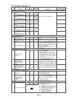
5-1 Monitor parameters
No. Parameter Unit
Remarks
D00 – Output frequency monitor
0 Output frequency in Hz
Hz
1 Output frequency in %
%
will display when the drive is in standby.
displays while the DC brake is in action.
is displayed during pick up.
D01 – Frequency setting monitor
0 Set frequency in Hz
Hz
The currently selected frequency setting value is displayed.
1 Set frequency in %
%
The max. frequency is displayed as 100%.
D02 – Current monitor
0 Output
current
(Amps)
A
will display when the drive is in standby.
1 Output current (%)
%
The motor rated current is displayed as 100%.
2 Overload (OL-1) monitor
%
OL-1 functions when this value reaches 100%.
3 Motor overload (OL-3)
monitor
%
The OL-3 operates when at 100%.
4 Heatsink temperature
°C
Depending on the capacity, OHT.1 functions at 95°C or 120°C or more.
7 U phase output current
amps
A
8 V phase output current
amps
A
9 W phase output current
amps
A
will display when the gate is closed.
The correct value is not displayed during pick-up or during automatic tuning.
D03 – Voltage monitor
0 DC voltage
V
Displays the voltage of the DC link circuit in the main circuit.
1 Output voltage (command)
V
Displays output voltage command. The display may differ from the actual output
voltage. It depends on the power supply voltage.
will display when the gate is
closed.
2 Output power
kW
Displays the inverter’s output power.
will display when the gate is closed.
3 Carrier frequency
The current carrier frequency is displayed.
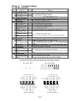
D04 – Sequence status
0-3 Sequence status-Input 1
to 4
4-7 Sequence status-Output 1
to 4
The ON/OFF state of the internal sequence data will display.
The correspondence of each LED/LCD segment and signal is shown in the next
page.
D05 – Minor fault monitor
0 Minor fault failure monitor
The internal minor fault status will display.
1 Hardware detection fault
status
The status of the fault signal detected by the hardware is displayed.
Sequence Input(D04-0)
REV
JOG
EXC
BRAKE
COP
Sequence Input(D04-1)
RUN
RESET
EMS
AFS1
CPASS
IPASS
CSEL
AFS2
AFS3
PROG
CFS
S3
SE
FUP
FDW
BUP
S2
S1
S0
PICK
AUXDV
IVLM
BDW
S5
S6
S7
MBRK_ans
(For V24-OP1)
(For V24-OP2)
A state of ON/ off of the internal sequence data is indicated as follows.
Содержание VAT300 Series
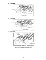
Страница 10: ...EN 8 h X075K0 X090K0 i X110K0 X132K0 j X160K0 X200K0 Fig 2 3 b cont Terminal block wiring ...
Страница 110: ...FR 8 h X075K0 X090K0 i X110K0 X132K0 j X160K0 X200K0 Fig 2 3 b cont Repérage des bornes ...
Страница 143: ...IT 8 h X075K0 X090K0 i X110K0 X132K0 j X160K0 X200K0 Fig 2 3 b Collegamenti alla morsettiera di potenza ...


