EN-23
7) During automatic tuning execution
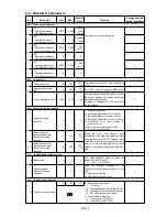
The progression state can be confirmed with D22-0.
8) Normal completion of automatic tuning
When the automatic tuning ends normally, the "LCL" LED will change from a flicker to a stable
light. The "RUN" LED will change from a stable light to the OFF state.
Refer to section 4-5 for the adjustment items.
9) Abnormal completion of automatic tuning
If automatic tuning ends abnormally, the "FLT" LED will turn ON and a message will appear.
Investigate and check according to the error codes.
Refer to section 4-6-2 for details on the error codes.
4-6-2 Automatic tuning error messages
If automatic tuning ends abnormally, the following message will appear. Investigate and confirm the
state following the error code.
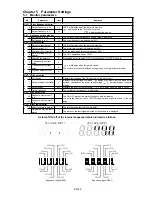
E00:ATT-n (for U30 V24OP1),
(for U30 V24OP2) n
:
Automatic tuning step
No.
Cause and remedy
n=1 The motor may not be connected correctly.
Check the connection.
The B00 and B01 parameters may not be set correctly.
Check the parameter setting.
n=2 The B00 and B01 parameters may not be set correctly.
Check the parameter setting.
n=3 The load and machine may not be separated.
Separate the load and machine.
Lengthen the acceleration time (A01-0).
Lengthen the deceleration time (A01-1).
If the motor vibrates, adjust the torque stabilizing gain (B18-2).
Normally, the default value (1.00) is set, but increase the setting value in increments of
approx. 0.05 according to the state of hunting. Please return to regulated value (1.00) of a
set value once, and reduce it by carving about 0.05 when the hunting phenomenon is not
controlled even in case of maximum value (4.00) .
n=4 The load and machine may not be separated.
Separate the load and machine.
If the motor vibrates, increase the torque stabilizing gain (B18-2).
Normally, the default value (1.00) is set, but increase the setting value in increments of
approx. 0.05 according to the state of hunting. Please return to regulated value (1.00) of a
set value once, and reduce it by carving about 0.05 when the hunting phenomenon is not
controlled even in case of maximum value (4.00) .
n=5 When the motor does not stop
Increase the acceleration/deceleration time (A01-0, A01-1).
When the motor does stop
The B00 and B01 parameters may not be set correctly.
Check the parameter setting.
n=6 The B00 and B01 parameters may not be set correctly.
Check the parameter setting.
n=8 Indicates that the output voltage did not stabilize for 1 second or more during magnetic pole
position estimation for the PM motor.
n=9 Indicates that the PM motor magnetic pole estimation did not end normally even after
retrying three times.
U pper level :The steps required for tuning are
indicated (lit).
Low er level :The finished steps are indicated (lit).
The step currently being executed is
indicated with a flicker.
(For V 24-O P 1)
(For V 24-O P 2)
Содержание VAT300 Series
Страница 10: ...EN 8 h X075K0 X090K0 i X110K0 X132K0 j X160K0 X200K0 Fig 2 3 b cont Terminal block wiring ...
Страница 110: ...FR 8 h X075K0 X090K0 i X110K0 X132K0 j X160K0 X200K0 Fig 2 3 b cont Repérage des bornes ...
Страница 143: ...IT 8 h X075K0 X090K0 i X110K0 X132K0 j X160K0 X200K0 Fig 2 3 b Collegamenti alla morsettiera di potenza ...


