66
489 GENERATOR MANAGEMENT RELAY – COMMUNICATIONS GUIDE
N
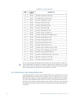
Note
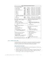
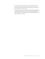
The counters cannot be cleared with the Freeze/Clear function codes (9/10). Instead, the
control relay output block points can be used to clear groups of counters. There is only one
copy of each counter, so clearing a counter via Modbus or the front panel display causes
the corresponding DNP counter point to be cleared and vice-versa.
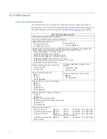
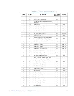
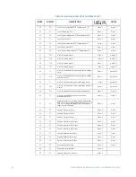
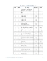
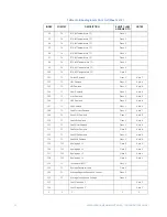
CG.5.4 Analog Input / Input Change (Objects 30/32)
In the following table, the Format column indicates that the associated data point format is
determined by the entry in
Data Formats
on page CG–42. For example, an “F1” format is
described in that table as a (16-bit) unsigned value without any decimal places. Therefore,
the value read should be interpreted in this manner. Many of the values reported by the
489 have a size of 32-bits and have had their upper and lower 16-bit components assigned
to separate points. Where indicated, refer to the appropriate note following the table for
more detail.
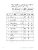
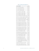
20
50000
Number of Reactive Power Trips
21
50000
Number of Reverse Power Trips
22
50000
Number of Underpower Trips
23
50000
Number of Stator RTD Trips
24
50000
Number of Bearing RTD Trips
25
50000
Number of Other RTD Trips
26
50000
Number of Ambient RTD Trips
27
50000
Number of Thermal Model Trips
28
50000
Number of Inadvertent Energization Trips
29
50000
Number of Analog Input 1 Trips
30
50000
Number of Analog Input 2 Trips
31
50000
Number of Analog Input 3 Trips
32
50000
Number of Analog Input 4 Trips
33
50000
Number of Loss of Excitation Circle 1 Trips
34
50000
Number of Loss of Excitation Circle 2 Trips
35
50000
Number of Ground Directional Trips
36
50000
Number of High Set Phase Overcurrent Trips
37
50000
Number of Distance Zone 1 Trips
38
50000
Number of Distance Zone 2 Trips
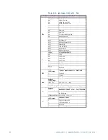
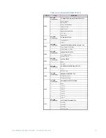
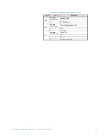
Table CG–7: Counters Point List
INDEX
ROLLOVER
POINT
DESCRIPTION
Содержание Multilin 489
Страница 2: ......
Страница 4: ...CGTOC II 489 GENERATOR MANAGEMENT RELAY COMMUNICATIONS GUIDE TABLE OF CONTENTS...

