Quick Start Instructions
Listed below are the basic steps for installing GE MDS entraNET transceivers. Refer to the
appropriate sections in the manual for detailed information.
1.
Initial Checkout
• Set the equipment up in a tabletop arrangement as described in
2 TABLETOP SETUP AND
EVALUATION
,
(beginning on Page 15)
.
• Follow all steps to ensure proper cable connections and unit configuration. As a minimum, Access
Points must have the following programmed: IP Address, IP Network identifier, and Radio Network
Address. (RF output power and Password should also be reviewed and set if necessary.) Remote
radios normally require only a Radio Network Address to be set. (Note: The Remote Radio Net-
work Address
must
match that of the AP.)
• Connect data equipment to the transceivers. Use LAN/ETH ports for Ethernet systems, or COM2
ports for Serial data systems.
• Verify proper exchange of data communications by viewing the LEDs. The following indications
should be seen on the LED panel within 30 seconds of startup:
PWR
—Lit continuously
LINK
—Lit continuously
ETH
—Lit continuously (unless Sleep is activated)
COM2
—Blinking to indicate exchange of data communications
2.
Endpoint Connectivity (PING) Test—for Ethernet Systems Only
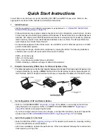
• For Ethernet systems, verify the link integrity between the Access Point and endpoint devices con-
nected to Remotes by issuing a
PING
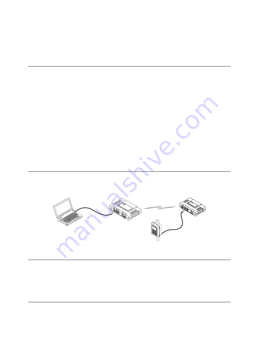
command from the AP. Below is a basic setup diagram for
the PING test. (NOTE: Endpoint devices must have a compatible IP address for this test to work.)
COM1
ETH
PWR
LINK
LAN
PORT
PC RUNNING PING UTILITY
ACCESS POINT
ETHERNET REMOTE
ETH
PORT
ETHERNET ENDPOINT
(Device Being Pinged)
STRAIGHT THROUGH
CABLE
CROSS-OVER
CABLE
LAN
COM1
COM2
PWR
LINK
Invisible place holder
3.
Set Configuration of AP and Remote Radios
• Refer to
3 AP MANAGEMENT
beginning on Page 29
for details on connecting to the AP and
using the built-in menu system. Refer to
4 REMOTE RADIO MANAGEMENT
beginning on
Page 99
for details on programming Remotes.
• If you have a large number of radios to configure, a configuration script may be used to speed the
process. See
USING CONFIGURATION SCRIPTS
beginning on Page 181
for details.
4.
Install the Equipment in the Field
• Refer to
6 INSTALLATION
beginning on Page 147
for details on site selection, mounting, cabling,
and antenna/feedline recommendations.
• After basic installation, optimize the performance of the radio network following the recommenda-
tions beginning on Page 160.
Содержание MDS entraNET 900
Страница 10: ...LA N CO M1 CO M2 PW R LIN K viii MDS entraNET Technical Manual 05 4055A01 Rev E...
Страница 12: ...2 MDS entraNET Technical Manual 05 4055A01 Rev E LA N CO M1 CO M2 PW R LIN K...
Страница 24: ...14 MDS entraNET Technical Manual 05 4055A01 Rev E LA N CO M1 CO M2 PW R LIN K...
Страница 26: ...16 MDS entraNET Technical Manual 05 4055A01 Rev E LA N CO M1 CO M2 PW R LIN K...
Страница 38: ...28 MDS entraNET Technical Manual 05 4055A01 Rev E LA N CO M1 CO M2 PW R LIN K...
Страница 110: ...100 MDS entraNET Technical Manual 05 4055A01 Rev E LA N CO M1 CO M2 PW R LIN K...
Страница 130: ...120 MDS entraNET Technical Manual 05 4055A01 Rev E LA N CO M1 CO M2 PW R LIN K...
Страница 156: ...146 MDS entraNET Technical Manual 05 4055A01 Rev E LA N CO M1 CO M2 PW R LIN K...
Страница 158: ...148 MDS entraNET Technical Manual 05 4055A01 Rev E LA N CO M1 CO M2 PW R LIN K...
Страница 176: ...166 MDS entraNET Technical Manual 05 4055A01 Rev E LA N CO M1 CO M2 PW R LIN K...
Страница 186: ...176 MDS entraNET Technical Manual 05 4055A01 Rev E LA N CO M1 CO M2 PW R LIN K...
Страница 188: ...178 MDS entraNET Technical Manual 05 4055A01 Rev E LA N CO M1 CO M2 PW R LIN K...
Страница 204: ...194 MDS entraNET Technical Manual 05 4055A01 Rev E LA N CO M1 CO M2 PW R LIN K...
Страница 218: ...I 8 MDS entraNET Technical Manual 05 4055A01 Rev E...
Страница 220: ...GE MDS LLC Rochester NY 14620 General Business 1 585 242 9600 FAX 1 585 242 9620 Web www gemds com 175 Science Parkway...

