2
Chapter 1
•
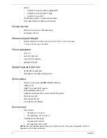
WLAN:
•
Intel® WiFi Link 5100 802.11a/b/g/Draft-N*
•
Intel® WiFi Link 5100 802.11a/b/g*
•
Intel® WiFi Link 1000*
•
WPAN: Bluetooth® 2.1+Enhanced Data Rate*
•
LAN: Gigabit Ethernet; Wake-on-LAN ready
Privacy control
•
BIOS user, supervisor, HDD passwords
•
Kensington lock slot
Dimensions and Weight
•
285 (W) 208.9 (D) 28.5/34.5 (H) mm (11.22 x 8.22 x 1.12/1.36 inches)
•
1.72 kg (3.79 lbs.) (non-3G SKU)
Power subsystem
•
ACPI 3.0
•
62.16 W 5600 mAh
•
3-pin 30 W AC adapter
•
ENERGY STAR®*
Special keys and controls
•
84-/85-/88-key keyboard
•
Multi-gesture touchpad pointing device
I/O interface
•
Multi-in-1 card reader (SD/MMC/MS/MS PRO/xD)
•
USB 2.0 port
•
HDMI™ port with HDCP support
•
External display (VGA) port
•
Headphones/speaker/line-out jack with S/PDIF support
•
Microphone-in jack
•
Ethernet (RJ-45) port
•
DC-in jack for AC adapter
Environment
•
Temperature:
•
Operating: 5 °C to 35 °C
•
Non-operating: -20 °C to 65 °C
•
Humidity (non-condensing):
•
Operating: 20% to 80%
•
Non-operating: 20% to 80%
NOTE:
The specifications listed above are for reference only. The exact configuration of the PC
depends on the model purchased.
Содержание EC14T Series
Страница 6: ...vi ...
Страница 10: ...x Table of Contents ...
Страница 13: ...Chapter 1 3 System Block Diagram ...
Страница 32: ...22 Chapter 1 ...
Страница 48: ...38 Chapter 2 ...
Страница 61: ...Chapter 3 51 4 Remove the one 1 screw 5 Remove the 3G module Step Screw Quantity Screw Type 3G Module M2 3 1 ...
Страница 65: ...Chapter 3 55 4 Unlock the FPC 5 Remove the FPC and keyboard ...
Страница 67: ...Chapter 3 57 4 Partially open the LCD module 5 Remove the hinge cap ...
Страница 83: ...Chapter 3 73 6 Remove the CRT cable ...
Страница 89: ...Chapter 3 79 3 Grasp the speaker housings pull the cables free of the adhesive removing the speaker module ...
Страница 96: ...86 Chapter 3 7 Pry up the bezel bottom edge 8 Remove the bezel ...
Страница 106: ...96 Chapter 3 4 Remove the hinge ...
Страница 108: ...98 Chapter 3 7 Remove the antenna cable from the retention guide hooks 8 Peel the left antenna foil off the cover ...
Страница 109: ...Chapter 3 99 9 Peel the antenna off the adhesive 10 Remove the antenna cable from the retention guide hooks ...
Страница 110: ...100 Chapter 3 11 Remove both antenna cables from the cover ...
Страница 124: ...114 Chapter 3 6 Replace the screw covers 7 Insert the stylus ...
Страница 139: ...Chapter 3 129 8 Lock the I O board connector Replacing the Button Board 1 Replace the button board ...
Страница 149: ...Chapter 3 139 4 Press down the keyboard top edge Replacing the 3G Module 1 Replace the 3G module ...
Страница 153: ...Chapter 3 143 2 Replace the HDD in the bay 3 Adhere the black tape 4 Replace the HDD FPC ...
Страница 155: ...Chapter 3 145 2 Press firmly around the edges of the module cover 3 Tighten the five 5 captive screws ...
Страница 157: ...Chapter 3 147 3 Lock the battery Replacing the Dummy Card 1 Insert the dummy card into the slot ...
Страница 158: ...148 Chapter 3 ...
Страница 206: ...196 Appendix B ...
Страница 208: ...198 ...
Страница 211: ...201 ...
Страница 212: ...202 ...


