


16
Chapter 1
Disks
2
2
1
1
2
1
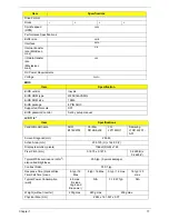
Spindle
speed
(RPM)
5400
Performance Specifications
Buffer size
8MB
Interface
SATA
Internal
transfer
rate (Gbits/
sec., max)
3GB/s maximum
1.5GB/s
maximum
I/O data
transfer
rate
(Mbytes/
sec max)
875 Mbits/s maximum
845 Mbits/s
maximum
775Mbits/s
maximum
729Mbits/s
maximum
DC Power Requirements
Voltage
+5.0V ± 5%.
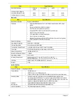
Item
Specifications
Vendor & Model
Name
Toshiba
MK1655GSX
Toshiba
MK2555GSX
Toshiba
MK3255GSX
Toshiba
MK5055GSX
Capacity (GB)
160
250
320
500
Bytes per sector
512
512
512
512
Data heads
2
2
4
4
Drive Format
Disks
1
1
2
2
Spindle speed
(RPM)
5400
Performance Specifications
Buffer size
8MB
Interface
SATA
Internal transfer
rate (Mbits/sec,
max)
363 ~ 952 typical
I/O data transfer
rate
(Mbytes/sec
max)
300
DC Power Requirements
Voltage
5V ±5%
Item
Specifications
Vendor & Model
Name
Western Digital
WD1600BEVT-
22ZCTO
Western Digital
WD2500BEVT-22ZCT0
Western Digital
WD3200BEVT-22ZCT0
Western Digital
WD5000BEVT-22ZAT0
Capacity (GB)
160
250
320
500
Bytes per sector
512
Data heads
2
4
3
4
Item
Specifications
Содержание EC14T Series
Страница 6: ...vi ...
Страница 10: ...x Table of Contents ...
Страница 13: ...Chapter 1 3 System Block Diagram ...
Страница 32: ...22 Chapter 1 ...
Страница 48: ...38 Chapter 2 ...
Страница 61: ...Chapter 3 51 4 Remove the one 1 screw 5 Remove the 3G module Step Screw Quantity Screw Type 3G Module M2 3 1 ...
Страница 65: ...Chapter 3 55 4 Unlock the FPC 5 Remove the FPC and keyboard ...
Страница 67: ...Chapter 3 57 4 Partially open the LCD module 5 Remove the hinge cap ...
Страница 83: ...Chapter 3 73 6 Remove the CRT cable ...
Страница 89: ...Chapter 3 79 3 Grasp the speaker housings pull the cables free of the adhesive removing the speaker module ...
Страница 96: ...86 Chapter 3 7 Pry up the bezel bottom edge 8 Remove the bezel ...
Страница 106: ...96 Chapter 3 4 Remove the hinge ...
Страница 108: ...98 Chapter 3 7 Remove the antenna cable from the retention guide hooks 8 Peel the left antenna foil off the cover ...
Страница 109: ...Chapter 3 99 9 Peel the antenna off the adhesive 10 Remove the antenna cable from the retention guide hooks ...
Страница 110: ...100 Chapter 3 11 Remove both antenna cables from the cover ...
Страница 124: ...114 Chapter 3 6 Replace the screw covers 7 Insert the stylus ...
Страница 139: ...Chapter 3 129 8 Lock the I O board connector Replacing the Button Board 1 Replace the button board ...
Страница 149: ...Chapter 3 139 4 Press down the keyboard top edge Replacing the 3G Module 1 Replace the 3G module ...
Страница 153: ...Chapter 3 143 2 Replace the HDD in the bay 3 Adhere the black tape 4 Replace the HDD FPC ...
Страница 155: ...Chapter 3 145 2 Press firmly around the edges of the module cover 3 Tighten the five 5 captive screws ...
Страница 157: ...Chapter 3 147 3 Lock the battery Replacing the Dummy Card 1 Insert the dummy card into the slot ...
Страница 158: ...148 Chapter 3 ...
Страница 206: ...196 Appendix B ...
Страница 208: ...198 ...
Страница 211: ...201 ...
Страница 212: ...202 ...