


158
Chapter 4
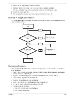
c.
Select the microphone type from the list and click
Next
.
d.
Follow the onscreen prompts to complete the test.
8.
If the Issue is still not resolved, see “Online Support Information” on page 165.
HDD Not Operating Correctly
If the
HDD
does not operate correctly, perform the following actions one at a time to correct the problem.
1.
Disconnect all external devices.
2.
Run a complete virus scan using up-to-date software to ensure the computer is virus free.
3.
Run the Windows Vista Startup Repair Utility:
a.
insert the Windows Vista Operating System DVD in the ODD and restart the computer.
b.
When prompted, press any key to start to the operating system DVD.
c.
The
Install
Windows
screen displays. Click
Next
.
d.
Select
Repair your computer
.
e.
The
System
Recovery
Options
screen displays. Click
Next
.
f.
Select the appropriate operating system, and click
Next
.
NOTE:
Click
Load
Drivers
if controller drives are required.
g.
Select
Startup
Repair
.
h.
Startup Repair attempts to locate and resolve issues with the computer.
i.
When complete, click
Finish
.
If an issue is discovered, follow the onscreen information to resolve the problem.
4.
Run the Windows Memory Diagnostic Tool. For more information see Windows Help and Support.
5.
Restart the computer and press F2 to enter the BIOS Utility. Check the BIOS settings are correct and that
CD/DVD drive is set as the first boot device on the Boot menu.
6.
Ensure all cables and jumpers on the HDD and ODD are set correctly.
7.
Remove any recently added hardware and associated software.
8.
Run the Windows Disk Defragmenter. For more information see Windows Help and Support.
9.
Run Windows Check Disk by entering
chkdsk
/r
from a command prompt. For more information see
Windows Help and Support.
10.
Restore system and file settings from a known good date using
System
Restore
.
If the issue is not fixed, repeat the preceding steps and select an earlier time and date.
11.
Replace the HDD. See “Disassembly Process” on page 34.
Содержание EC14T Series
Страница 6: ...vi ...
Страница 10: ...x Table of Contents ...
Страница 13: ...Chapter 1 3 System Block Diagram ...
Страница 32: ...22 Chapter 1 ...
Страница 48: ...38 Chapter 2 ...
Страница 61: ...Chapter 3 51 4 Remove the one 1 screw 5 Remove the 3G module Step Screw Quantity Screw Type 3G Module M2 3 1 ...
Страница 65: ...Chapter 3 55 4 Unlock the FPC 5 Remove the FPC and keyboard ...
Страница 67: ...Chapter 3 57 4 Partially open the LCD module 5 Remove the hinge cap ...
Страница 83: ...Chapter 3 73 6 Remove the CRT cable ...
Страница 89: ...Chapter 3 79 3 Grasp the speaker housings pull the cables free of the adhesive removing the speaker module ...
Страница 96: ...86 Chapter 3 7 Pry up the bezel bottom edge 8 Remove the bezel ...
Страница 106: ...96 Chapter 3 4 Remove the hinge ...
Страница 108: ...98 Chapter 3 7 Remove the antenna cable from the retention guide hooks 8 Peel the left antenna foil off the cover ...
Страница 109: ...Chapter 3 99 9 Peel the antenna off the adhesive 10 Remove the antenna cable from the retention guide hooks ...
Страница 110: ...100 Chapter 3 11 Remove both antenna cables from the cover ...
Страница 124: ...114 Chapter 3 6 Replace the screw covers 7 Insert the stylus ...
Страница 139: ...Chapter 3 129 8 Lock the I O board connector Replacing the Button Board 1 Replace the button board ...
Страница 149: ...Chapter 3 139 4 Press down the keyboard top edge Replacing the 3G Module 1 Replace the 3G module ...
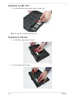
Страница 153: ...Chapter 3 143 2 Replace the HDD in the bay 3 Adhere the black tape 4 Replace the HDD FPC ...
Страница 155: ...Chapter 3 145 2 Press firmly around the edges of the module cover 3 Tighten the five 5 captive screws ...
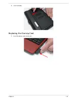
Страница 157: ...Chapter 3 147 3 Lock the battery Replacing the Dummy Card 1 Insert the dummy card into the slot ...
Страница 158: ...148 Chapter 3 ...
Страница 206: ...196 Appendix B ...
Страница 208: ...198 ...
Страница 211: ...201 ...
Страница 212: ...202 ...


