


184
Chapter 6
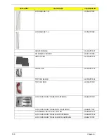
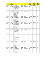
LCD
LCD MODULE ASSY NLED11.6WXGAG PB RED W/
ANTENNA
6M.BGU07.001
LCD MODULE ASSY NLED11.6WXGAG PB RED W/3G
ANTENNA
6M.BGV07.001
LCD MODULE ASSY NLED11.6WXGAG PB BLACK W/
ANTENNA
6M.BGW07.001
LCD MODULE ASSY NLED11.6WXGAG PB BLACK W/3G
ANTENNA
6M.BGY07.001
LCD MODULE ASSY NLED11.6WXGAG GW BLACK W/
ANTENNA
6M.WGV07.001
LCD MODULE ASSY NLED11.6WXGAG GW RED W/
ANTENNA
6M.WHJ07.001
LCD MODULE ASSY NLED11.6WXGAG GW BLACK W/3G
ANTENNA
6M.WHN07.001
LCD MODULE ASSY NLED11.6WXGAG GW RED W/3G
ANTENNA
6M.WHP07.001
LCD PANEL W/TOUCH PANEL
LED LCD SAMSUNG 11.6" WXGAG LTN116AT01-A01 W/
TOUCH PANEL
56.PND07.001
LED LCD AUO 11.6" WXGAG B116XW02 V0 1A (3G) W/
TOUCH PANEL
56.PND07.002
LED LCD LPL 11.6" WXGAG LP116WH1-TLA1 W/TOUCH
PANEL
56.PND07.003
LED LCD CMO 11.6" WXGAG N116B6-L02 C2 W/TOUCH
PANEL
56.PND07.004
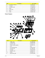
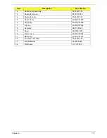
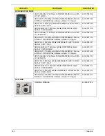
MAINBOARD
Mainboard JM12_MS Intel G45 LF SU7300 w/o 3G
MB.PN306.001
Mainboard JM12_MS Intel G45 LF SU7300 w/ 3G
MB.PN306.002
Mainboard JM12_MS Intel G45 LF SU4100 w/o 3G
MB.PNA06.001
Mainboard JM12_MS Intel G45 LF SU4100 w/ 3G
MB.PNA06.002
Mainboard JM12_MS Intel G45 LF SU2300 WO/3G W/O RAM
MB.PND06.001
Mainboard JM12_MS Intel G45 LF SU2300 W/3G W/O RAM
MB.PND06.002
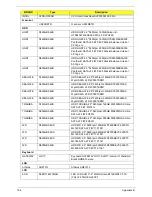
CATEGORY
PARTNAME
ACERPARTNO.
Содержание EC14T Series
Страница 6: ...vi ...
Страница 10: ...x Table of Contents ...
Страница 13: ...Chapter 1 3 System Block Diagram ...
Страница 32: ...22 Chapter 1 ...
Страница 48: ...38 Chapter 2 ...
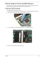
Страница 61: ...Chapter 3 51 4 Remove the one 1 screw 5 Remove the 3G module Step Screw Quantity Screw Type 3G Module M2 3 1 ...
Страница 65: ...Chapter 3 55 4 Unlock the FPC 5 Remove the FPC and keyboard ...
Страница 67: ...Chapter 3 57 4 Partially open the LCD module 5 Remove the hinge cap ...
Страница 83: ...Chapter 3 73 6 Remove the CRT cable ...
Страница 89: ...Chapter 3 79 3 Grasp the speaker housings pull the cables free of the adhesive removing the speaker module ...
Страница 96: ...86 Chapter 3 7 Pry up the bezel bottom edge 8 Remove the bezel ...
Страница 106: ...96 Chapter 3 4 Remove the hinge ...
Страница 108: ...98 Chapter 3 7 Remove the antenna cable from the retention guide hooks 8 Peel the left antenna foil off the cover ...
Страница 109: ...Chapter 3 99 9 Peel the antenna off the adhesive 10 Remove the antenna cable from the retention guide hooks ...
Страница 110: ...100 Chapter 3 11 Remove both antenna cables from the cover ...
Страница 124: ...114 Chapter 3 6 Replace the screw covers 7 Insert the stylus ...
Страница 139: ...Chapter 3 129 8 Lock the I O board connector Replacing the Button Board 1 Replace the button board ...
Страница 149: ...Chapter 3 139 4 Press down the keyboard top edge Replacing the 3G Module 1 Replace the 3G module ...
Страница 153: ...Chapter 3 143 2 Replace the HDD in the bay 3 Adhere the black tape 4 Replace the HDD FPC ...
Страница 155: ...Chapter 3 145 2 Press firmly around the edges of the module cover 3 Tighten the five 5 captive screws ...
Страница 157: ...Chapter 3 147 3 Lock the battery Replacing the Dummy Card 1 Insert the dummy card into the slot ...
Страница 158: ...148 Chapter 3 ...
Страница 206: ...196 Appendix B ...
Страница 208: ...198 ...
Страница 211: ...201 ...
Страница 212: ...202 ...


