18
Chapter 1
Bluetooth
Audio Interface
Electrical Interface
1 channel
LVDS
3.3V LVDS
LVDS
LVDS
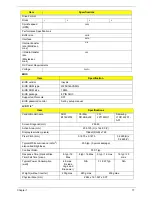
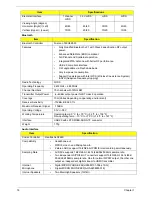
Viewing Angle (degree)
Horizontal (Right) / (Left)
Vertical (Upper) / (Lower)
45/45
10/30
45/45
20/45
30/30
10/20
45/45
15/35
Item
Specification
Bluetooth Controller
Foxconn T60H928.33
Features
•
Fully Qualified Bluetooth v2.1 with Class 2 specification RF output
power.
•
Enhanced Data Rate (EDR) compliant.
•
Full Piconet and Scatternet operation.
•
Integrated PIFA Antenna with better RF performance.
•
USB 2.0 compliant interface.
•
F/W upgradable via Flash downloads.
•
Very low power consumption.
•
Support Coexistence with Intel WCS (Wireless Coexistence System)
& AFH (Adaptive Frequency Hopping)
Radio Technology
FHSS
Operating Frequency
2.402GHz ~ 2.480GHz
Channel Numbers
79 channels with 1MHz BW
Transmitter Output Power
-6~4dBm output power for BT class 2 operation
Coverage
10m (Varies depending on operating environment)
Receiver Sensitivity
-75dBm, BER<0.1%
Maximum Receiver Signal
-10dBm
Operating Voltage
3.3V+/-0.3V
Working Temperature
Operating temp: 0 °C to +70 °C (+32 °F to +158 °F)
Non-operating temp: -10 °C to +75°C (+14 °F to +167 °F)
Interface
USB2.0 with JST SM08B-SURS-TF connector
Weight 1.75g
Item
Specification
Codec Controller
Realtek ALC269X
Compatibility
•
Headphone-out
•
S/PDIF, Line-In and Microphone-In.
•
2 stereo ADCs support 16/20/24-bit PCM format recording simultaneously.
Sampling Rate
•
All DACs supports 16/20/24-bit, 44.1k/48k/96k/192kHz sample rate.
•
Two independent S/PDIF-OUT converters support 16/20/24-bit, 44.1k/48k/
88.2k/96k/192kHz sample rate. One for normal S/PDIF output, the other one
output an independent digital stream to HDMI transmitter.
Internal
Microphone
•
Digital MICRO PHONE ZK2(HFM-M101-006-L19-G)
•
Digital MICRO PHONE ZK2(A-OA2408FM-018)
Internal Speakers
•
Two Med-High Speakers (1W/4Ù)
Item
Specifications
Содержание EC14T Series
Страница 6: ...vi ...
Страница 10: ...x Table of Contents ...
Страница 13: ...Chapter 1 3 System Block Diagram ...
Страница 32: ...22 Chapter 1 ...
Страница 48: ...38 Chapter 2 ...
Страница 61: ...Chapter 3 51 4 Remove the one 1 screw 5 Remove the 3G module Step Screw Quantity Screw Type 3G Module M2 3 1 ...
Страница 65: ...Chapter 3 55 4 Unlock the FPC 5 Remove the FPC and keyboard ...
Страница 67: ...Chapter 3 57 4 Partially open the LCD module 5 Remove the hinge cap ...
Страница 83: ...Chapter 3 73 6 Remove the CRT cable ...
Страница 89: ...Chapter 3 79 3 Grasp the speaker housings pull the cables free of the adhesive removing the speaker module ...
Страница 96: ...86 Chapter 3 7 Pry up the bezel bottom edge 8 Remove the bezel ...
Страница 106: ...96 Chapter 3 4 Remove the hinge ...
Страница 108: ...98 Chapter 3 7 Remove the antenna cable from the retention guide hooks 8 Peel the left antenna foil off the cover ...
Страница 109: ...Chapter 3 99 9 Peel the antenna off the adhesive 10 Remove the antenna cable from the retention guide hooks ...
Страница 110: ...100 Chapter 3 11 Remove both antenna cables from the cover ...
Страница 124: ...114 Chapter 3 6 Replace the screw covers 7 Insert the stylus ...
Страница 139: ...Chapter 3 129 8 Lock the I O board connector Replacing the Button Board 1 Replace the button board ...
Страница 149: ...Chapter 3 139 4 Press down the keyboard top edge Replacing the 3G Module 1 Replace the 3G module ...
Страница 153: ...Chapter 3 143 2 Replace the HDD in the bay 3 Adhere the black tape 4 Replace the HDD FPC ...
Страница 155: ...Chapter 3 145 2 Press firmly around the edges of the module cover 3 Tighten the five 5 captive screws ...
Страница 157: ...Chapter 3 147 3 Lock the battery Replacing the Dummy Card 1 Insert the dummy card into the slot ...
Страница 158: ...148 Chapter 3 ...
Страница 206: ...196 Appendix B ...
Страница 208: ...198 ...
Страница 211: ...201 ...
Страница 212: ...202 ...


