


Chapter 4
151
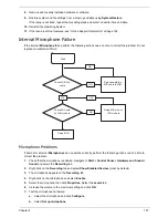
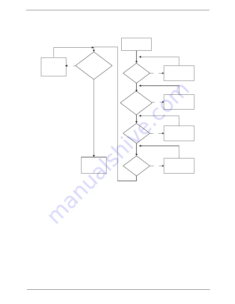
No Display Issue
If the
Display
doesn’t work, perform the following actions one at a time to correct the problem. Do not replace
non-defective FRUs:
No POST or Video
If the POST or video doesn’t display, perform the following actions one at a time to correct the problem.
1.
Make sure that the internal display is selected. On this notebook model, switching between the internal
display and the external display is done by pressing
Fn+F5
. Reference Product pages for specific model
procedures.
2.
Make sure the computer has power by checking at least one of the following occurs:
•
Fans start up
•
Status LEDs light up
If there is no power, see “Power On Issue” on page 150.
3.
Drain any stored power by removing the power cable and battery and holding down the power button for
10 seconds. Reconnect the power and reboot the computer.
4.
Connect an external monitor to the computer and switch between the internal display and the external
display is by pressing
Fn+F5
(on this model).
If the POST or video appears on the external display, see “LCD Failure” on page 153.
5.
Disconnect power and all external devices including port replicators or docking stations. Remove any
memory cards and CD/DVD discs. Restart the computer.
START
Power On ?
No
Go to No Power
troubleshooting
step
Replace external
DDRAM module
Remove and
replace thermal
module
Replace the
main board
Reconnect
SDRAM Module
LCD Module OK?
Replace LCD
Panel and
Cable
Ext. DDRAM module
connected properly?
Ext. DDRAM
module functional?
CPU Thermal
Module properly
connected?
No
No
No
No
Содержание EC14T Series
Страница 6: ...vi ...
Страница 10: ...x Table of Contents ...
Страница 13: ...Chapter 1 3 System Block Diagram ...
Страница 32: ...22 Chapter 1 ...
Страница 48: ...38 Chapter 2 ...
Страница 61: ...Chapter 3 51 4 Remove the one 1 screw 5 Remove the 3G module Step Screw Quantity Screw Type 3G Module M2 3 1 ...
Страница 65: ...Chapter 3 55 4 Unlock the FPC 5 Remove the FPC and keyboard ...
Страница 67: ...Chapter 3 57 4 Partially open the LCD module 5 Remove the hinge cap ...
Страница 83: ...Chapter 3 73 6 Remove the CRT cable ...
Страница 89: ...Chapter 3 79 3 Grasp the speaker housings pull the cables free of the adhesive removing the speaker module ...
Страница 96: ...86 Chapter 3 7 Pry up the bezel bottom edge 8 Remove the bezel ...
Страница 106: ...96 Chapter 3 4 Remove the hinge ...
Страница 108: ...98 Chapter 3 7 Remove the antenna cable from the retention guide hooks 8 Peel the left antenna foil off the cover ...
Страница 109: ...Chapter 3 99 9 Peel the antenna off the adhesive 10 Remove the antenna cable from the retention guide hooks ...
Страница 110: ...100 Chapter 3 11 Remove both antenna cables from the cover ...
Страница 124: ...114 Chapter 3 6 Replace the screw covers 7 Insert the stylus ...
Страница 139: ...Chapter 3 129 8 Lock the I O board connector Replacing the Button Board 1 Replace the button board ...
Страница 149: ...Chapter 3 139 4 Press down the keyboard top edge Replacing the 3G Module 1 Replace the 3G module ...
Страница 153: ...Chapter 3 143 2 Replace the HDD in the bay 3 Adhere the black tape 4 Replace the HDD FPC ...
Страница 155: ...Chapter 3 145 2 Press firmly around the edges of the module cover 3 Tighten the five 5 captive screws ...
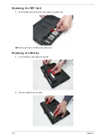
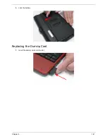
Страница 157: ...Chapter 3 147 3 Lock the battery Replacing the Dummy Card 1 Insert the dummy card into the slot ...
Страница 158: ...148 Chapter 3 ...
Страница 206: ...196 Appendix B ...
Страница 208: ...198 ...
Страница 211: ...201 ...
Страница 212: ...202 ...


