Appendix B
193
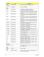
Test Compatible Components
This computer’s compatibility is tested and verified by Acer’s internal testing department. All of its system
functions are tested under Windows
®
7 environment.
Refer to the following lists for components, adapter cards, and peripherals which have passed these tests.
Regarding configuration, combination and test procedures, please refer to the Compatibility Test Report
released by the Acer Mobile System Testing Department.
BRAND
Type
Description
3G
UNDP-1
3G UNDP-1
Qualcomm
Gobi1000-Verizon
Qualcomm Gobi1000-Verizon
Accessory
SJM12_MS GW Protection
Bag
Accessory SJM12_MS +SJM13_MS GW Protection Bag
SJM12_MS PB Protection
Bag
Accessory SSJM13_MS PB Protection Bag
USB Bridge Dongle
Accessory USB Bridge dongle device - XSYNC
Adapter
DELTA
30W
Adapter DELTA 30W 19V 1.7x5.5x11 Black ADP-30JH
BA LF
HIPRO
30W
Adapter HIPRO 30W 19V 1.7x5.5x11 Black HP-A0301R3
B1LF LF
LITE-ON
30W
Adapter LITE-ON 30W 19V 1.7x5.5x11 Black PA-1300-
04AC LF
Audio Codec
Realtek
ALC269X
Realtek Audio Codec ALC269X
Battery
SANYO
6CELL2.8
Battery SANYO UM-2009F Li-Ion 3S2P SANYO 6 cell
5600mAh Main COMMON
SIMPLO
6CELL2.8
Battery SIMPLO UM-2009F Li-Ion 3S2P SAMSUNG 6
cell 5600mAh Main COMMON ID:UM09F70
Bluetooth
Foxconn
BT 2.1
Foxconn Bluetooth BRM 2046 BT2.1 (T60H928.33) f/
w:861
Camera
Chicony
0.3M LDV
Chicony 0.3M LDV Lilac_3GA ( CNF9042-G )
Chicony
0.3M LDV
Chicony Camera Lilac_2G
Liteon
0.3M LDV
Liteon Camera Lily_2G
Suyin
0.3M LDV
Suyin Camera Rose_2G
Card Reader
5 in 1-Build in
5 in 1-Build in MS, MS Pro, SD, SC, XD
CPU
INTEL
CMSU2300B
CPU Intel Celeron SU2300 BGA 1.2G 1M 800 10W R-0
INTEL
PMDSU4100B
CPU Intel Core2Dual SU4100 2M 800
Appendix B
Содержание EC14T Series
Страница 6: ...vi ...
Страница 10: ...x Table of Contents ...
Страница 13: ...Chapter 1 3 System Block Diagram ...
Страница 32: ...22 Chapter 1 ...
Страница 48: ...38 Chapter 2 ...
Страница 61: ...Chapter 3 51 4 Remove the one 1 screw 5 Remove the 3G module Step Screw Quantity Screw Type 3G Module M2 3 1 ...
Страница 65: ...Chapter 3 55 4 Unlock the FPC 5 Remove the FPC and keyboard ...
Страница 67: ...Chapter 3 57 4 Partially open the LCD module 5 Remove the hinge cap ...
Страница 83: ...Chapter 3 73 6 Remove the CRT cable ...
Страница 89: ...Chapter 3 79 3 Grasp the speaker housings pull the cables free of the adhesive removing the speaker module ...
Страница 96: ...86 Chapter 3 7 Pry up the bezel bottom edge 8 Remove the bezel ...
Страница 106: ...96 Chapter 3 4 Remove the hinge ...
Страница 108: ...98 Chapter 3 7 Remove the antenna cable from the retention guide hooks 8 Peel the left antenna foil off the cover ...
Страница 109: ...Chapter 3 99 9 Peel the antenna off the adhesive 10 Remove the antenna cable from the retention guide hooks ...
Страница 110: ...100 Chapter 3 11 Remove both antenna cables from the cover ...
Страница 124: ...114 Chapter 3 6 Replace the screw covers 7 Insert the stylus ...
Страница 139: ...Chapter 3 129 8 Lock the I O board connector Replacing the Button Board 1 Replace the button board ...
Страница 149: ...Chapter 3 139 4 Press down the keyboard top edge Replacing the 3G Module 1 Replace the 3G module ...
Страница 153: ...Chapter 3 143 2 Replace the HDD in the bay 3 Adhere the black tape 4 Replace the HDD FPC ...
Страница 155: ...Chapter 3 145 2 Press firmly around the edges of the module cover 3 Tighten the five 5 captive screws ...
Страница 157: ...Chapter 3 147 3 Lock the battery Replacing the Dummy Card 1 Insert the dummy card into the slot ...
Страница 158: ...148 Chapter 3 ...
Страница 206: ...196 Appendix B ...
Страница 208: ...198 ...
Страница 211: ...201 ...
Страница 212: ...202 ...


