


Chapter 4
161
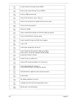
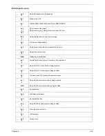
Post Codes
These tables describe the Post Codes and components of the POST process.
Sec:
NO_EVICTION_MODE_DEBUG EQU 1 (CommonPlatform\sec\Ia32\SecCore.inc)
Memory:
DEBUG_BIOS EQU 1 (Chipset\Alviso\MemoryInitAsm\IA32\IMEMORY.INC)
0x
C2
MTRR setup
0x
C3
Enable cache
0x
C4
Establish cache tags
0x
C5
Enter NEM, Place the BSP in No Fill mode, set CR0.CD = 1, CR0.NW = 0.
0xCF
Cache Init Finished
0x
A0
First memory check point
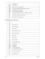
0x
01
Enable MCHBAR
0x
02
Check for DRAM initialization interrupt and reset fail
0x
03
Verify all DIMMs are DDR or DDR2 and unbuffered
0x
04
Detect an improper warm reset and handle
0x
05
Detect if ECC SO-DIMMs are present in the system
0x
06
Verify all DIMMs are single or double sided and not asymmetric
0x
07
Verify all DIMMs are x8 or x16 width
0x
08
Find a common CAS latency between the DIMMS and the MCH
0x
09
Determine the memory frequency and CAS latency to program
0x
10
Determine the smallest common TRAS for all DIMMs
0x
11
Determine the smallest common TRP for all DIMMs
0x
12
Determine the smallest common TRCD for all DIMMs
0x
13
Determine the smallest refresh period for all DIMMs
Содержание EC14T Series
Страница 6: ...vi ...
Страница 10: ...x Table of Contents ...
Страница 13: ...Chapter 1 3 System Block Diagram ...
Страница 32: ...22 Chapter 1 ...
Страница 48: ...38 Chapter 2 ...
Страница 61: ...Chapter 3 51 4 Remove the one 1 screw 5 Remove the 3G module Step Screw Quantity Screw Type 3G Module M2 3 1 ...
Страница 65: ...Chapter 3 55 4 Unlock the FPC 5 Remove the FPC and keyboard ...
Страница 67: ...Chapter 3 57 4 Partially open the LCD module 5 Remove the hinge cap ...
Страница 83: ...Chapter 3 73 6 Remove the CRT cable ...
Страница 89: ...Chapter 3 79 3 Grasp the speaker housings pull the cables free of the adhesive removing the speaker module ...
Страница 96: ...86 Chapter 3 7 Pry up the bezel bottom edge 8 Remove the bezel ...
Страница 106: ...96 Chapter 3 4 Remove the hinge ...
Страница 108: ...98 Chapter 3 7 Remove the antenna cable from the retention guide hooks 8 Peel the left antenna foil off the cover ...
Страница 109: ...Chapter 3 99 9 Peel the antenna off the adhesive 10 Remove the antenna cable from the retention guide hooks ...
Страница 110: ...100 Chapter 3 11 Remove both antenna cables from the cover ...
Страница 124: ...114 Chapter 3 6 Replace the screw covers 7 Insert the stylus ...
Страница 139: ...Chapter 3 129 8 Lock the I O board connector Replacing the Button Board 1 Replace the button board ...
Страница 149: ...Chapter 3 139 4 Press down the keyboard top edge Replacing the 3G Module 1 Replace the 3G module ...
Страница 153: ...Chapter 3 143 2 Replace the HDD in the bay 3 Adhere the black tape 4 Replace the HDD FPC ...
Страница 155: ...Chapter 3 145 2 Press firmly around the edges of the module cover 3 Tighten the five 5 captive screws ...
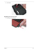
Страница 157: ...Chapter 3 147 3 Lock the battery Replacing the Dummy Card 1 Insert the dummy card into the slot ...
Страница 158: ...148 Chapter 3 ...
Страница 206: ...196 Appendix B ...
Страница 208: ...198 ...
Страница 211: ...201 ...
Страница 212: ...202 ...


