


Chapter 4
169
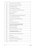
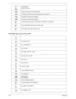
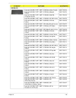
Each SmmDriver entry point used in 80_PORT
0x
89
MONITOR_KEY
0x8A
PLATFORM_BDS
0x8B
FAULT_TOLERANT_WRITE
0x8C
UPDATE_DISPATCHER
0x8D
CHINESE
0x8
E
TPM_S3_Resume
0x
8F
0x
90
USB_EHCI
SNP_32_64
0x
91
PXE_BC
0x
92
PXE_DHCP4
0x
93
EBC
0x94~0x9F
RESERVED
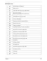
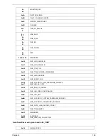
0xA0
DXE_H2O_DEBUG_IO
0xA1
DXE_H2O_DEBUG_IO
0xA2
DXE_TPM_TCG
0xA3
DXE_TPM_PHYSICAL_PRESENCE
0xA4
DXE_OEM_SERVICE
0xA5
DXE_EVENT_LOG
0xA6
0xA7
DXE_ SECURITY_HDD_PASSWORD_SERVICE
DXE_LAN_ASF_INIT
0xA8
DXE_BUS_PCI_SERIAL
0xA9
DXE_LAN_IDER_CONTROLLER
0xAA
DXE_LAN_AMT
0xAB
DXE_ SECURITY_SYSTEM_PASSWORD_SERVICE
0xAC
DXE_ SECURITY_ PASSWORD_CONSOLE
0xAD
DXE_ DATA_HUB_RECORD_POLICY
0xAE
DXE_TPM_DRIVER
0xAF
RESERVED
0xB0
0xB1
JAPANESE
DXE_UNICODE_COLLACTION
0xC0
SMM_ACCESS
Содержание EC14T Series
Страница 6: ...vi ...
Страница 10: ...x Table of Contents ...
Страница 13: ...Chapter 1 3 System Block Diagram ...
Страница 32: ...22 Chapter 1 ...
Страница 48: ...38 Chapter 2 ...
Страница 61: ...Chapter 3 51 4 Remove the one 1 screw 5 Remove the 3G module Step Screw Quantity Screw Type 3G Module M2 3 1 ...
Страница 65: ...Chapter 3 55 4 Unlock the FPC 5 Remove the FPC and keyboard ...
Страница 67: ...Chapter 3 57 4 Partially open the LCD module 5 Remove the hinge cap ...
Страница 83: ...Chapter 3 73 6 Remove the CRT cable ...
Страница 89: ...Chapter 3 79 3 Grasp the speaker housings pull the cables free of the adhesive removing the speaker module ...
Страница 96: ...86 Chapter 3 7 Pry up the bezel bottom edge 8 Remove the bezel ...
Страница 106: ...96 Chapter 3 4 Remove the hinge ...
Страница 108: ...98 Chapter 3 7 Remove the antenna cable from the retention guide hooks 8 Peel the left antenna foil off the cover ...
Страница 109: ...Chapter 3 99 9 Peel the antenna off the adhesive 10 Remove the antenna cable from the retention guide hooks ...
Страница 110: ...100 Chapter 3 11 Remove both antenna cables from the cover ...
Страница 124: ...114 Chapter 3 6 Replace the screw covers 7 Insert the stylus ...
Страница 139: ...Chapter 3 129 8 Lock the I O board connector Replacing the Button Board 1 Replace the button board ...
Страница 149: ...Chapter 3 139 4 Press down the keyboard top edge Replacing the 3G Module 1 Replace the 3G module ...
Страница 153: ...Chapter 3 143 2 Replace the HDD in the bay 3 Adhere the black tape 4 Replace the HDD FPC ...
Страница 155: ...Chapter 3 145 2 Press firmly around the edges of the module cover 3 Tighten the five 5 captive screws ...
Страница 157: ...Chapter 3 147 3 Lock the battery Replacing the Dummy Card 1 Insert the dummy card into the slot ...
Страница 158: ...148 Chapter 3 ...
Страница 206: ...196 Appendix B ...
Страница 208: ...198 ...
Страница 211: ...201 ...
Страница 212: ...202 ...


