4
Chapter 1
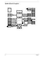
System Block Diagram
F A N & T H E R M A L
P 3
P OW E R
8L H DI
P C B ST A C K UP
USB
DM I x 4
800/1066 M H z F SB
SA T A 0
C R T
C onnector
DDR 2-SODI M M
L V DS
L E D P anel
C onnector
V G A
667/800M H Z DDR I I
2.5H DD
L P C
C P U C or e
SY ST E M 5V /3V
P 21
P 22
P 3,4
P G 5,6,7,8,9,10
P 15
P 20
NO R T H B R I DG E
M icr o-F C B G A 956/10W
Penr yn SF F UL V DC /SC
SOUTH BRIDGE
I C H 9-M SF F
C antiga SF F G S45
DDR P ower
P 24
L A Y E R 4 : V C C
L A Y E R 3 : I N1
L A Y E R 1 : T O P
L A Y E R 5 : I N2
L A Y E R 2 : G ND
L A Y E R 6 : I N3
L A Y E R 7 : G ND
L A Y E R 8 : B OT
DDR 2-SODI M M
P 16
H DM I
C onnector
T M DS
H DM I L evel Shifter
P 22
P or t 0
On B oar d USB 2
C
o
nne
c
to
r
P 21
On B oar d USB 3
P or t 1
C ar d R eader
A lcor A U6433
P or t 3
On B oar d USB 0
P 20
P or t 6
M I NI C A R D 1
P 19
P or t 7
M I NI C A R D 2
P 19
P or t 2
C C D
P 22
P or t 4
B ule T ooth
P 21
P or t 5
C PU
cahnge A
cahnge B
P 22
P G 11,12,13,14
G L A N
A ther os A R 8131L
C onnector
P 21
P C I E 4
M I NI C A R D 1
C onnector
P 19
M I NI C A R D 2
C onnector
P 19
P C I E 5
P C I E
P C I E 1
P 19
SI M C A R D
C onnector
C onnector
I H DA
C ODE C
P 17
P 21
R ealtek A L C 269X
L ine Out/M I C
Speaker C onnector
P 21
Speaker
Digital M I C
L E D P anel
C onnector
P 22
E C
P 18
W inbond W PC E 775L A 0DG
2M bytes
P 18
F L A SH
SP I
C onnector
P 21
T ouchP A D
P S/2
8x16
P 21
K eyboar d
C onnector
C K 505 (Q F N-64)
C L OC K
P G 2
R T 8206B
I SL 6261A
P 25
R T 8207A
P 26
P 27
V C C P 1.05V
R T 8202A
P 28
1.5V
Dischar ge
G 9334/A O4466
P 28
1.5V _S5
R T 9025
P 28
P 29
G F X
I SL 6263A
XTAL
Y2
14.318MHZ
XTAL
Y3
32.768KHZ
XTAL
Y4
32.768KHZ
XTAL
Y2
25MHZ
XTAL
Y1
12MHZ
Содержание EC14
Страница 6: ...VI ...
Страница 10: ...X Table of Contents ...
Страница 34: ...24 Chapter 1 ...
Страница 50: ...40 Chapter 2 ...
Страница 60: ...50 Chapter 3 5 Pull the memory module out ...
Страница 71: ...Chapter 3 61 8 Lift up and pull the button board to main board FCC free ...
Страница 75: ...Chapter 3 65 4 Lift off the LCD Board 5 Unlock and remove the LED board FCC from the mainboard ...
Страница 89: ...Chapter 3 79 4 Lift the LCD panel out lifting the bottom of the panel first ...
Страница 93: ...Chapter 3 83 5 Remove the antennas completely ...
Страница 99: ...Chapter 3 89 3 Apply adhesive and stick the microphone down ...
Страница 104: ...94 Chapter 3 Replacing the RTC Battery 1 Place the RTC battery into the holding clips on the main board ...
Страница 108: ...98 Chapter 3 3 Connect the speaker connector ...
Страница 116: ...106 Chapter 3 5 Relay the WLAN cables around and through the lower case ...
Страница 127: ...Chapter 3 117 4 Place the HDD cover in from one edge 5 Tighten the four captive screws ...
Страница 128: ...118 Chapter 3 Replacing the Battery 1 Slide the battery into position 2 Close the locking latch ...
Страница 129: ...Chapter 3 119 Replace the Dummy Card Push the dummy card into the slot until it clicks into place ...
Страница 130: ...120 Chapter 3 ...
Страница 170: ...160 ...


