34
Chapter 2
DOS Flash Utility
Perform the following steps to use the DOS Flash Utility:
1.
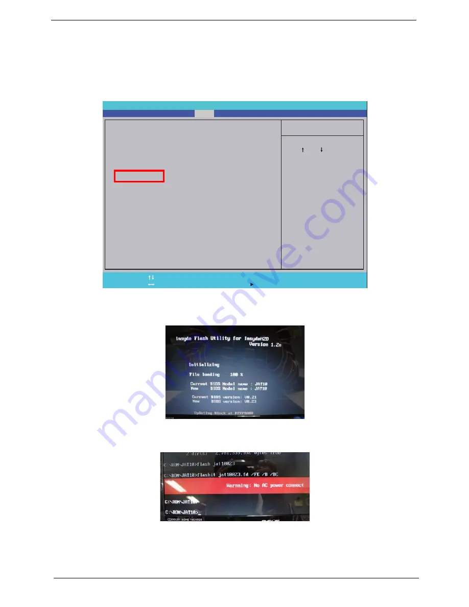
Press F2 during boot to enter the Setup Menu.
2.
Select
Boot Menu
to modify the boot priority order, for example, if using USB HDD to Update BIOS, move
USB HDD to position 1.
3.
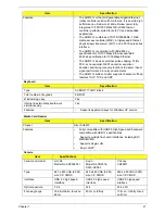
Execute the
FLASH.BAT
batch file to update BIOS. Or enter C:\
Flash it bios ver.fd/dc
The flash process begins as shown.
4.
In flash BIOS, the message
Please do not remove AC Power Source
displays.
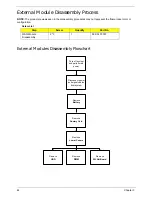
NOTE:
If the AC power is not connected, the following message displays.
Plug in the AC power to continue.
5.
Flash is complete when the message Flash programming complete displays.
I t e m S p e c i f i c H e l p
U s e < > o r < > t o s e l e c t
a d e v i c e , t h e n p r e s s
< F 5 > t o m o v e i t d o w n t h e
l i s t , o r < F 6 > t o m o v e
i t u p t h e l i s t . P r e s s
< E s c > t o e s c a p e t h e m e n u
F 1
E S C
H e l p
E x i t
S e l e c t I t e m
S e l e c t M e n u
C h a n g e Va l u e s
S e l e c t
S u b M e n u
E n t e r
F 9
F 10
S e t u p D e f a u l t
S a v e a n d E x i t
B o o t p r i o r i t y o r d e r :
1 . I D E 0 : H i t a c h i H T S 5 4 5 0 3 2 B 9 A 3 0 0
2 . I D E 1 :
3 . N e t w o r k B o o t : A t h e r o s B o o t A g e n t
4 . U S B H D D
5 . U S B C D R O M :
6 . U S B F D D :
B o o t p r i o r i t y o r d e r :
1 . I D E 0 : H i t a c h i H T S 5 4 5 0 3 2 B 9 A 3 0 0
2 . I D E 1 :
3 . N e t w o r k B o o t : A t h e r o s B o o t A g e n t
4 . U S B H D D
5 . U S B C D R O M :
6 . U S B F D D :
F 5 / F 6
I n s y d e H 2 0 S e t u p U t i l i t y R e v . 3 . 5
Information
Main
Boot
Exit
Security
Содержание EC14
Страница 6: ...VI ...
Страница 10: ...X Table of Contents ...
Страница 34: ...24 Chapter 1 ...
Страница 50: ...40 Chapter 2 ...
Страница 60: ...50 Chapter 3 5 Pull the memory module out ...
Страница 71: ...Chapter 3 61 8 Lift up and pull the button board to main board FCC free ...
Страница 75: ...Chapter 3 65 4 Lift off the LCD Board 5 Unlock and remove the LED board FCC from the mainboard ...
Страница 89: ...Chapter 3 79 4 Lift the LCD panel out lifting the bottom of the panel first ...
Страница 93: ...Chapter 3 83 5 Remove the antennas completely ...
Страница 99: ...Chapter 3 89 3 Apply adhesive and stick the microphone down ...
Страница 104: ...94 Chapter 3 Replacing the RTC Battery 1 Place the RTC battery into the holding clips on the main board ...
Страница 108: ...98 Chapter 3 3 Connect the speaker connector ...
Страница 116: ...106 Chapter 3 5 Relay the WLAN cables around and through the lower case ...
Страница 127: ...Chapter 3 117 4 Place the HDD cover in from one edge 5 Tighten the four captive screws ...
Страница 128: ...118 Chapter 3 Replacing the Battery 1 Slide the battery into position 2 Close the locking latch ...
Страница 129: ...Chapter 3 119 Replace the Dummy Card Push the dummy card into the slot until it clicks into place ...
Страница 130: ...120 Chapter 3 ...
Страница 170: ...160 ...


