


Chapter 2
29
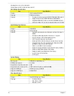
1.
Use the
↑
and
↓
keys to highlight the Set Supervisor Password parameter and press the
Enter
key. The
Set Supervisor Password box appears:
2.
Type a password in the “Enter New Password” field. The password length can not exceeds 8
alphanumeric characters (A-Z, a-z, 0-9, not case sensitive). Retype the password in the “Confirm New
Password” field.
IMPORTANT:
Be very careful when typing your password because the characters do not appear on the screen.
3.
Press
Enter
.
After setting the password, the computer sets the User Password parameter to “Set”.
4.
If desired, you can opt to enable the Password on boot parameter.
5.
When you are done, press F10 to save the changes and exit the BIOS Setup Utility.
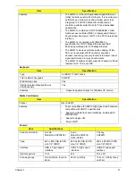
Removing a Password
Follow these steps:
1.
Use the
↑
and
↓
keys to highlight the Set Supervisor Password parameter and press the
Enter
key. The
Set Password box appears:
2.
Type the current password in the Enter Current Password field and press
Enter
.
3.
Press
Enter
twice
without
typing anything in the Enter New Password and Confirm New Password fields.
The computer then sets the Supervisor Password parameter to “Clear”.
4.
When you have changed the settings, press
u
to save the changes and exit the BIOS Setup Utility.
S e t S u p e r v i s o r P a s s w o r d
E n t e r N e w P a s s w o r d [ ]
[ ]
C o n f i r m N e w P a s s w o r d [ ]
S e t S u p e r v i s o r P a s s w o r d
E n t e r C u r r e n t P a s s w o r d [ ]
[ ]
E n t e r N e w P a s s w o r d [ ]
C o n f i r m N e w P a s s w o r d [ ]
[ ]
Содержание EC14
Страница 6: ...VI ...
Страница 10: ...X Table of Contents ...
Страница 34: ...24 Chapter 1 ...
Страница 50: ...40 Chapter 2 ...
Страница 60: ...50 Chapter 3 5 Pull the memory module out ...
Страница 71: ...Chapter 3 61 8 Lift up and pull the button board to main board FCC free ...
Страница 75: ...Chapter 3 65 4 Lift off the LCD Board 5 Unlock and remove the LED board FCC from the mainboard ...
Страница 89: ...Chapter 3 79 4 Lift the LCD panel out lifting the bottom of the panel first ...
Страница 93: ...Chapter 3 83 5 Remove the antennas completely ...
Страница 99: ...Chapter 3 89 3 Apply adhesive and stick the microphone down ...
Страница 104: ...94 Chapter 3 Replacing the RTC Battery 1 Place the RTC battery into the holding clips on the main board ...
Страница 108: ...98 Chapter 3 3 Connect the speaker connector ...
Страница 116: ...106 Chapter 3 5 Relay the WLAN cables around and through the lower case ...
Страница 127: ...Chapter 3 117 4 Place the HDD cover in from one edge 5 Tighten the four captive screws ...
Страница 128: ...118 Chapter 3 Replacing the Battery 1 Slide the battery into position 2 Close the locking latch ...
Страница 129: ...Chapter 3 119 Replace the Dummy Card Push the dummy card into the slot until it clicks into place ...
Страница 130: ...120 Chapter 3 ...
Страница 170: ...160 ...


