84
Chapter 3
LCD Reassembly Procedure
NOTE:
Adhesive is required to be added at various steps to cables and components. Locations of adhesive to
be added is designated with a:
NOTE:
During manufacture a cyanoacrylate glue is used provided by Holdtite Adhesives LTD. This is not a
specified requirement. The reassembler is free to select an alternative appropriate adhesive.
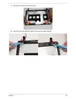
Replacing the Antennas
1.
Relay the cables around the module edge for the left antenna.
2.
Relay the cables around the module edge for the right antenna.
Содержание EC14
Страница 6: ...VI ...
Страница 10: ...X Table of Contents ...
Страница 34: ...24 Chapter 1 ...
Страница 50: ...40 Chapter 2 ...
Страница 60: ...50 Chapter 3 5 Pull the memory module out ...
Страница 71: ...Chapter 3 61 8 Lift up and pull the button board to main board FCC free ...
Страница 75: ...Chapter 3 65 4 Lift off the LCD Board 5 Unlock and remove the LED board FCC from the mainboard ...
Страница 89: ...Chapter 3 79 4 Lift the LCD panel out lifting the bottom of the panel first ...
Страница 93: ...Chapter 3 83 5 Remove the antennas completely ...
Страница 99: ...Chapter 3 89 3 Apply adhesive and stick the microphone down ...
Страница 104: ...94 Chapter 3 Replacing the RTC Battery 1 Place the RTC battery into the holding clips on the main board ...
Страница 108: ...98 Chapter 3 3 Connect the speaker connector ...
Страница 116: ...106 Chapter 3 5 Relay the WLAN cables around and through the lower case ...
Страница 127: ...Chapter 3 117 4 Place the HDD cover in from one edge 5 Tighten the four captive screws ...
Страница 128: ...118 Chapter 3 Replacing the Battery 1 Slide the battery into position 2 Close the locking latch ...
Страница 129: ...Chapter 3 119 Replace the Dummy Card Push the dummy card into the slot until it clicks into place ...
Страница 130: ...120 Chapter 3 ...
Страница 170: ...160 ...


