


400 SERIES INSTALLATION MANUAL
Page 5-5
190-00140-02
Rev Q
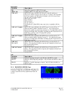
5.2.3 MAIN SYSTEM CONFIG Page
Select the MAIN SYSTEM CONFIG Page (see Figure 5-
3). This page allows you to configure the Fuel and Terrain
options.
Fuel
Select
Fuel
in the
CONFIGURE
field to select the FUEL
TYPE (
AV Gas, Jet A, or Jet B)
Selection Description
AV gas
The aircraft is using Aviation gas (5.8 lbs./gal.)
Jet A
The aircraft is using Jet A or Jet A-1 fuel (6.7 lbs./gal.)
Jet B
The aircraft is using Jet B (JP-4) fuel (6.5 lbs./gal.)
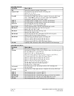
Terrain
Select
Terrain
in the
CONFIGURE
field (see Figure 5-4)
to select the TERRAIN TYPE (
NONE or TERRAIN
).
To test the Terrain Data Card, highlight the
TEST CARD
field and press the ENT key. Verify that the
TEST CARD
field indicates “PASS”. A “FAIL” condition indicates that
the Terrain Data Card is unusable. The HW CONFIG field
displays what type of Map Board is installed in the 400
Series unit.
The HW CONFIG field will display "
TERRAIN
" if the
appropriate hardware is installed to enable the TERRAIN functionality. If TERRAIN hardware is installed,
the HW CONFIG field will display "
No TERRAIN
".
TERRAIN TYPE
Selection Description
None
No terrain functionality is installed
TERRAIN
The unit is configured for TERRAIN capability
400 Series TERRAIN units may be manually configured for
TERRAIN
or
None.
If an incorrect hardware/software combination is entered, the message "HARDWARE CONFLICT!
MANUALLY ENTER TERRAIN TYPE" is displayed on the MAIN SYSTEM CONFIG page beside the
part number field. Also, a “Terrain configuration conflict” message will be issued in NORMAL mode if an
incorrect hardware/software combination is selected.
NOTE
The 400 Series TERRAIN functionality is not designed nor approved for use in helicopters.
Figure 5-3. MAIN SYSTEM CONFIG
Page 1
Figure 5-4. MAIN SYSTEM CONFIG
Page 2
Содержание GNC 420
Страница 8: ...Page vi 400 SERIES INSTALLATION MANUAL Rev Q 190 00140 02 This page intentionally left blank ...
Страница 28: ...Page 3 8 400 SERIES INSTALLATION MANUAL Rev Q 190 00140 02 This page intentionally left blank ...
Страница 78: ...Page A 8 400 SERIES INSTALLATION MANUAL Rev Q 190 00140 02 This page intentionally left blank ...
Страница 80: ...Page B 2 400 SERIES INSTALLATION MANUAL Rev Q 190 00140 02 ...
Страница 81: ...400 SERIES INSTALLATION MANUAL Page B 3 190 00140 02 Rev Q ...
Страница 82: ...Page B 4 400 SERIES INSTALLATION MANUAL Rev Q 190 00140 02 ...
Страница 83: ...400 SERIES INSTALLATION MANUAL Page B 5 190 00140 02 Rev Q ...
Страница 84: ...Page B 6 400 SERIES INSTALLATION MANUAL Rev Q 190 00140 02 ...
Страница 85: ...400 SERIES INSTALLATION MANUAL Page B 7 190 00140 02 Rev Q ...
Страница 86: ...Page B 8 400 SERIES INSTALLATION MANUAL Rev Q 190 00140 02 ...
Страница 87: ...400 SERIES INSTALLATION MANUAL Page B 9 190 00140 02 Rev Q ...
Страница 88: ...Page B 10 400 SERIES INSTALLATION MANUAL Rev Q 190 00140 02 This page intentionally left blank ...
Страница 103: ...400 SERIES INSTALLATION MANUAL Page F 3 Page F 4 blank 190 00140 02 Rev Q Figure F 1 GA 56 Antenna Installation Drawing ...
Страница 104: ...400 SERIES INSTALLATION MANUAL Page F 5 Page F 6 blank 190 00140 02 Rev Q Figure F 2 GNS 430 Mounting Rack Dimensions ...
Страница 105: ...400 SERIES INSTALLATION MANUAL Page F 7 Page F 8 blank 190 00140 02 Rev Q Figure F 3 GNC 420 Mounting Rack Dimensions ...
Страница 106: ...400 SERIES INSTALLATION MANUAL Page F 9 Page F 10 blank 190 00140 02 Rev Q Figure F 4 GPS 400 Mounting Rack Dimensions ...
Страница 112: ...400 SERIES INSTALLATION MANUAL Page F 21 Page F 22 blank 190 00140 02 Rev Q Figure F 10 GNS 430 Typical Installation ...
Страница 113: ...400 SERIES INSTALLATION MANUAL Page F 23 Page F 24 blank 190 00140 02 Rev Q Figure F 11 GNC 420 Typical Installation ...
Страница 114: ...400 SERIES INSTALLATION MANUAL Page F 25 Page F 26 blank 190 00140 02 Rev Q Figure F 12 GPS 400 Typical Installation ...
Страница 116: ...400 SERIES INSTALLATION MANUAL Page F 29 Page F 30 blank 190 00140 02 Rev Q Figure F 14 Altimeter Interconnect ...
Страница 117: ...400 SERIES INSTALLATION MANUAL Page F 31 Page F 32 blank 190 00140 02 Rev Q Figure F 15 Main Indicator Interconnect ...
Страница 121: ...400 SERIES INSTALLATION MANUAL Page F 39 Page F 40 blank 190 00140 02 Rev Q Figure F 19 RS 232 Serial Data Interconnect ...
Страница 122: ...400 SERIES INSTALLATION MANUAL Page F 41 Page F 42 blank 190 00140 02 Rev Q Figure F 20 ARINC 429 EFIS Interconnect ...
Страница 130: ...400 SERIES INSTALLATION MANUAL Page F 57 Page F 58 blank 190 00140 02 Rev Q Figure F 28 Audio Panel Interconnect ...
Страница 131: ...400 SERIES INSTALLATION MANUAL Page F 59 Page F 60 blank 190 00140 02 Rev Q Figure F 29 VOR ILS Indicator Interconnect ...
Страница 132: ...400 SERIES INSTALLATION MANUAL Page F 61 Page F 62 blank 190 00140 02 Rev Q Figure F 30 RMI OBI Interconnect ...