


Page 5-20
400 SERIES INSTALLATION MANUAL
Rev Q
190-00140-02
5.3.7 VHF COM Check (GNC 420 and GNS 430 Only)
A flight test is recommended after the installation is complete to ensure satisfactory performance. To
check the communications transceiver, maintain an appropriate altitude and contact a ground station
facility at a range of at least 50 nautical miles. Contact a close ground station. Press the squelch disable
button to defeat the automatic squelch feature and listen for any unusual electrical noise which would
increase the squelch threshold. If possible, verify the communications capability on both the high and low
ends of the VHF COM band. It may be required by the governing regulatory agency to verify operation of
the COM transmitter and receiver at the extents of a ground facility’s service volume (e.g., FAA AC 23-
8A).
5.3.8 VOR/ILS Check (GNS 430 Only)
Select a VOR channel within a 40 nautical mile range. Listen to the VOR audio and verify that no
electrical interference such as magneto noise is present. Check the tone identifier filter operation. Fly
inbound or outbound on a selected VOR radial and check for proper LEFT/RIGHT, TO/FROM, and FLAG
indications. Check the VOR accuracy. Verify that the flag is hidden with a valid received station, and that
the flag is in view when there is not a received station. It may be required by the governing regulatory
agency to verify operation of the VOR receiver at the extents of a ground facility’s service volume (e.g.,
FAA AC 23-8A).
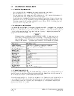
5.3.9 DME Tuning Check (GNS 430 Only)
Select a VOR/ILS channel that corresponds to (1) a DME station within a 40 nautical mile range, or (2) the
frequency of a DME ground tester. Verify that the DME locks on to the signal and a valid distance,
groundspeed and time are displayed.
5.3.10 TERRAIN System Check (For Units with TERRAIN Only)
Perform the TERRAIN verification check while on the ground. Before proceeding with this check, verify
the following:
x
The Terrain Data Card is inserted in the right card slot of the 400 Series TERRAIN unit.
x
Main Software Version is 5.01 or greater (shown on the first power-on page) is installed.
x
The 400 Series unit is configured for TERRAIN (see Section 5.2.3).
x
The 400 Series unit is capable of receiving a 3d-GPS position.
Perform the following steps to ensure the TERRAIN functional integrity:
1. Turn the 400 Series unit on in NORMAL mode.
2. Press the <ENT> button repeatedly to proceed through the self-test pages after power-on.
3. Verify that the “TER TEST” message is shown in the terrain annunciator field (lower-left portion of
the display).
4. Go to the TERRAIN page and verify the text “TERRAIN TEST” is displayed in the middle of the
TERRAIN page.
5. Verify that the “TER TEST” terrain annunciator message is removed; and
x
If a 3d-GPS signal is present, verify the terrain annunciator message is replaced with a black
empty square and a red/yellow terrain map is displayed on the TERRAIN page indicating the
relative altitude of the surrounding terrain.
x
If a 3d-GPS signal is not present, the terrain annunciator message is replaced by the text “TER
N/A” and the text “TERRAIN NOT AVAILABLE” is displayed on the TERRAIN page. If no 3d-
GPS signal is present, the 400 Series unit should be allowed to acquire the GPS position to display
the red/yellow terrain map.
If the message “TER FAIL” is displayed in the terrain annunciator message field at any time, the
TERRAIN function is not properly working and steps should be taken to investigate the problem.
Содержание GNC 420
Страница 8: ...Page vi 400 SERIES INSTALLATION MANUAL Rev Q 190 00140 02 This page intentionally left blank ...
Страница 28: ...Page 3 8 400 SERIES INSTALLATION MANUAL Rev Q 190 00140 02 This page intentionally left blank ...
Страница 78: ...Page A 8 400 SERIES INSTALLATION MANUAL Rev Q 190 00140 02 This page intentionally left blank ...
Страница 80: ...Page B 2 400 SERIES INSTALLATION MANUAL Rev Q 190 00140 02 ...
Страница 81: ...400 SERIES INSTALLATION MANUAL Page B 3 190 00140 02 Rev Q ...
Страница 82: ...Page B 4 400 SERIES INSTALLATION MANUAL Rev Q 190 00140 02 ...
Страница 83: ...400 SERIES INSTALLATION MANUAL Page B 5 190 00140 02 Rev Q ...
Страница 84: ...Page B 6 400 SERIES INSTALLATION MANUAL Rev Q 190 00140 02 ...
Страница 85: ...400 SERIES INSTALLATION MANUAL Page B 7 190 00140 02 Rev Q ...
Страница 86: ...Page B 8 400 SERIES INSTALLATION MANUAL Rev Q 190 00140 02 ...
Страница 87: ...400 SERIES INSTALLATION MANUAL Page B 9 190 00140 02 Rev Q ...
Страница 88: ...Page B 10 400 SERIES INSTALLATION MANUAL Rev Q 190 00140 02 This page intentionally left blank ...
Страница 103: ...400 SERIES INSTALLATION MANUAL Page F 3 Page F 4 blank 190 00140 02 Rev Q Figure F 1 GA 56 Antenna Installation Drawing ...
Страница 104: ...400 SERIES INSTALLATION MANUAL Page F 5 Page F 6 blank 190 00140 02 Rev Q Figure F 2 GNS 430 Mounting Rack Dimensions ...
Страница 105: ...400 SERIES INSTALLATION MANUAL Page F 7 Page F 8 blank 190 00140 02 Rev Q Figure F 3 GNC 420 Mounting Rack Dimensions ...
Страница 106: ...400 SERIES INSTALLATION MANUAL Page F 9 Page F 10 blank 190 00140 02 Rev Q Figure F 4 GPS 400 Mounting Rack Dimensions ...
Страница 112: ...400 SERIES INSTALLATION MANUAL Page F 21 Page F 22 blank 190 00140 02 Rev Q Figure F 10 GNS 430 Typical Installation ...
Страница 113: ...400 SERIES INSTALLATION MANUAL Page F 23 Page F 24 blank 190 00140 02 Rev Q Figure F 11 GNC 420 Typical Installation ...
Страница 114: ...400 SERIES INSTALLATION MANUAL Page F 25 Page F 26 blank 190 00140 02 Rev Q Figure F 12 GPS 400 Typical Installation ...
Страница 116: ...400 SERIES INSTALLATION MANUAL Page F 29 Page F 30 blank 190 00140 02 Rev Q Figure F 14 Altimeter Interconnect ...
Страница 117: ...400 SERIES INSTALLATION MANUAL Page F 31 Page F 32 blank 190 00140 02 Rev Q Figure F 15 Main Indicator Interconnect ...
Страница 121: ...400 SERIES INSTALLATION MANUAL Page F 39 Page F 40 blank 190 00140 02 Rev Q Figure F 19 RS 232 Serial Data Interconnect ...
Страница 122: ...400 SERIES INSTALLATION MANUAL Page F 41 Page F 42 blank 190 00140 02 Rev Q Figure F 20 ARINC 429 EFIS Interconnect ...
Страница 130: ...400 SERIES INSTALLATION MANUAL Page F 57 Page F 58 blank 190 00140 02 Rev Q Figure F 28 Audio Panel Interconnect ...
Страница 131: ...400 SERIES INSTALLATION MANUAL Page F 59 Page F 60 blank 190 00140 02 Rev Q Figure F 29 VOR ILS Indicator Interconnect ...
Страница 132: ...400 SERIES INSTALLATION MANUAL Page F 61 Page F 62 blank 190 00140 02 Rev Q Figure F 30 RMI OBI Interconnect ...