


400 SERIES INSTALLATION MANUAL
Page 3-7
190-00140-02
Rev
Q
3.7 RACK
INSTALLATION
1. The back plate of the rack may optionally be removed for ease of mounting in the aircraft
panel. To do so, remove the two #4-40 screws, tilt the back plate away from the tray, and then
slide the back plate to the side.
2. Figures 3-3, 3-4 and 3-5, starting on pages 3-11, 3-13, and 3-15, show outline dimensions for
the aviation rack for the various 400 Series units. Install the rack in a rectangular 6.320” x
2.700” hole (or gap between units) in the instrument panel (refer to Figure 3-9, page 3-23).
The lower-front lip of the rack should be flush with, or extend slightly beyond, the finished
aircraft panel.
CAUTION
If the front lip of the mounting rack is behind the surface of the aircraft panel,
the 400 Series unit connectors may not fully engage.
Make sure that no screw heads or other obstructions prevent the unit from fully engaging in the
rack (refer to the “Connector Engagement Test,” section 5.3.1, page 5-15). Exercise caution
when installing the rack into the instrument panel. The rack is designed to facilitate removal of
the 400 Series for use in Demo Mode outside the aircraft. Deformation of the rack may make it
difficult to install and remove the 400 Series unit.
3. Install the rack in the aircraft panel using six #6-32 flat head screws and six self-locking nuts.
The screws are inserted from the inside through the holes in the sides of the rack.
4. If the back plate was previously removed (see step #1), replace the back plate by positioning
the tabs on the back plate in the slots of the left side of the rack (viewing it from the cockpit)
and attaching it by replacing the two #4-40 screws.
3.8
400 SERIES UNIT INSERTION AND REMOVAL
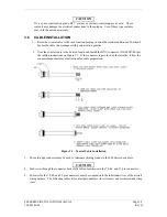
The 400 Series unit is installed in the rack by sliding it straight in until it stops, about 1 inch short of the
final position. A 3/32“ hex drive tool is then inserted into the access hole at the bottom of the unit face.
Rotate the hex tool clockwise while pressing on the left side of the bezel until the unit is firmly seated in
the rack. It may be necessary to insert the hex drive tool into the access hole and rotate the mechanism 90°
counterclockwise to ensure correct position prior to placing the unit in the rack.
To remove the unit from the rack, insert the hex drive tool into the access hole on the unit face and rotate
counterclockwise until the unit is forced out about 3/8 ” and can be freely pulled from the rack.
Be sure not to over tighten the unit into the rack. The application of hex drive tool torque exceeding
15 in•lbs can damage the locking mechanism.
3.9
COM ANTENNA INSTALLATION CHECK (GNC 420 AND GNS 430)
Check for insertion loss and VSWR (voltage standing wave ratio). VSWR should be checked with an in-
line type VSWR/wattmeter inserted in the coaxial transmission line between the transceiver and the
antenna. The VSWR/wattmeter should be inserted as close to the transceiver as possible. When rack and
harness buildup is performed in the shop, the coax termination may be provisioned by using a 6” inline
BNC connection. This would be an acceptable place to insert the VSWR/wattmeter. Any problem with the
antenna installation is most likely seen as high reflected power. A VSWR of 3:1 may result in up to a 50%
loss in transmit power.
Содержание GNC 420
Страница 8: ...Page vi 400 SERIES INSTALLATION MANUAL Rev Q 190 00140 02 This page intentionally left blank ...
Страница 28: ...Page 3 8 400 SERIES INSTALLATION MANUAL Rev Q 190 00140 02 This page intentionally left blank ...
Страница 78: ...Page A 8 400 SERIES INSTALLATION MANUAL Rev Q 190 00140 02 This page intentionally left blank ...
Страница 80: ...Page B 2 400 SERIES INSTALLATION MANUAL Rev Q 190 00140 02 ...
Страница 81: ...400 SERIES INSTALLATION MANUAL Page B 3 190 00140 02 Rev Q ...
Страница 82: ...Page B 4 400 SERIES INSTALLATION MANUAL Rev Q 190 00140 02 ...
Страница 83: ...400 SERIES INSTALLATION MANUAL Page B 5 190 00140 02 Rev Q ...
Страница 84: ...Page B 6 400 SERIES INSTALLATION MANUAL Rev Q 190 00140 02 ...
Страница 85: ...400 SERIES INSTALLATION MANUAL Page B 7 190 00140 02 Rev Q ...
Страница 86: ...Page B 8 400 SERIES INSTALLATION MANUAL Rev Q 190 00140 02 ...
Страница 87: ...400 SERIES INSTALLATION MANUAL Page B 9 190 00140 02 Rev Q ...
Страница 88: ...Page B 10 400 SERIES INSTALLATION MANUAL Rev Q 190 00140 02 This page intentionally left blank ...
Страница 103: ...400 SERIES INSTALLATION MANUAL Page F 3 Page F 4 blank 190 00140 02 Rev Q Figure F 1 GA 56 Antenna Installation Drawing ...
Страница 104: ...400 SERIES INSTALLATION MANUAL Page F 5 Page F 6 blank 190 00140 02 Rev Q Figure F 2 GNS 430 Mounting Rack Dimensions ...
Страница 105: ...400 SERIES INSTALLATION MANUAL Page F 7 Page F 8 blank 190 00140 02 Rev Q Figure F 3 GNC 420 Mounting Rack Dimensions ...
Страница 106: ...400 SERIES INSTALLATION MANUAL Page F 9 Page F 10 blank 190 00140 02 Rev Q Figure F 4 GPS 400 Mounting Rack Dimensions ...
Страница 112: ...400 SERIES INSTALLATION MANUAL Page F 21 Page F 22 blank 190 00140 02 Rev Q Figure F 10 GNS 430 Typical Installation ...
Страница 113: ...400 SERIES INSTALLATION MANUAL Page F 23 Page F 24 blank 190 00140 02 Rev Q Figure F 11 GNC 420 Typical Installation ...
Страница 114: ...400 SERIES INSTALLATION MANUAL Page F 25 Page F 26 blank 190 00140 02 Rev Q Figure F 12 GPS 400 Typical Installation ...
Страница 116: ...400 SERIES INSTALLATION MANUAL Page F 29 Page F 30 blank 190 00140 02 Rev Q Figure F 14 Altimeter Interconnect ...
Страница 117: ...400 SERIES INSTALLATION MANUAL Page F 31 Page F 32 blank 190 00140 02 Rev Q Figure F 15 Main Indicator Interconnect ...
Страница 121: ...400 SERIES INSTALLATION MANUAL Page F 39 Page F 40 blank 190 00140 02 Rev Q Figure F 19 RS 232 Serial Data Interconnect ...
Страница 122: ...400 SERIES INSTALLATION MANUAL Page F 41 Page F 42 blank 190 00140 02 Rev Q Figure F 20 ARINC 429 EFIS Interconnect ...
Страница 130: ...400 SERIES INSTALLATION MANUAL Page F 57 Page F 58 blank 190 00140 02 Rev Q Figure F 28 Audio Panel Interconnect ...
Страница 131: ...400 SERIES INSTALLATION MANUAL Page F 59 Page F 60 blank 190 00140 02 Rev Q Figure F 29 VOR ILS Indicator Interconnect ...
Страница 132: ...400 SERIES INSTALLATION MANUAL Page F 61 Page F 62 blank 190 00140 02 Rev Q Figure F 30 RMI OBI Interconnect ...