Page 3-6
400 SERIES INSTALLATION MANUAL
Rev Q
190-00140-02
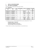
Table 3-1. Pin Contact Part Numbers
78 pin conn
(P4001)
44 pin conn
(P4006)
25 pin connector (P4002)
Shield ground
connector
Connector Type
High Density Pin Contact
Standard Density Socket Contact
.1” Pitch Card-edge
Wire Gauge
22-28 AWG
18 AWG
20-24 AWG
20-24 AWG
Garmin P/N
336-00021-00
336-00023-00
336-00022-00
336-00029-00
Military P/N
M39029/58-360
N/A
M39029/63-368
N/A
AMP 204370-2
N/A
205090-1
583853-4
Positronic M39029/58-360
FC6018D
M39029/63-368
N/A
ITT Cannon
030-2042-000
See Note 3
031-1007-042
N/A
Table 3-2. Recommended Crimp Tools (or equivalent)
Connector
Type
High
Density
Standard
Density
Wire Gauge
22-28 AWG
18 AWG
20-24 AWG
Hand
Crimping
Tool
Positioner Insertion/
Extraction
Tool
Positioner Insertion/
Extraction
Tool
Positioner Insertion/
Extraction
Tool
Military
P/N
M22520/2-01
M22520/2-09
M81969/1-04 N/A M81969/1-02
M22520/2-08
M81969/1-02
Positronic
9507
9502-3 M81969/1-04 9502-11 M81969/1-02 9502-5 M81969/1-02
ITT Cannon
995-0001-
584
995-0001-
739
N/A N/A N/A
995-0001-
604
980-2000-
426
AMP
601966-1 601966-6 91067-1
N/A
N/A 601966-5 91067-2
Daniels AFM8
K42
M81969/1-04
K774
M81969/1-02
K13-1
M81969/1-02
Astro
615717 615725
M81969/1-04 N/A M81969/1-02
615724
M81969/1-02
NOTES
1. Insertion/extraction tools from ITT Cannon are all plastic; others are plastic with metal tip.
2. Non-Garmin part numbers shown are not maintained by Garmin and consequently are subject
to change without notice.
3. Alternate contacts for 18 AWG wire: As an alternative to the Positronic contacts listed (and
provided in the installation kit), the installer may use contacts made by ITT Cannon under P/N
031-1007-001. These contacts require the use of a different crimp tool positioner than shown
in the table, with the part numbers as follows: Daniels P/N K250, Astro P/N 616245, or ITT
Cannon P/N 980-0005-722.
4. For the card-edge connector pin contacts, use AMP part number 90272-1 or equivalent
crimping tool.
To prevent a possible short across the pins in the wiring harness, use the Teflon shrink tubing P/N
312-00005-05 provided in Connector Kit 011-00351-00 (P4002) to cover the oversized power and
ground pin contacts P/N 336-00023-00 (pins 11, 12, 21, 22) that protrude from the back of the
connector shell. Before crimping the pins onto the wire:
1. Cut the tubing (312-00005-05) into 4 equal lengths.
2. Slide a short piece of the tubing over the wire.
3. Strip the wire and crimp the pin (336-00023-00) onto the wire.
4. Insert the pin into the connector shell.
5. Slide the tubing over the exposed portion of the pin and shrink using a heat gun.
Содержание GNC 420
Страница 8: ...Page vi 400 SERIES INSTALLATION MANUAL Rev Q 190 00140 02 This page intentionally left blank ...
Страница 28: ...Page 3 8 400 SERIES INSTALLATION MANUAL Rev Q 190 00140 02 This page intentionally left blank ...
Страница 78: ...Page A 8 400 SERIES INSTALLATION MANUAL Rev Q 190 00140 02 This page intentionally left blank ...
Страница 80: ...Page B 2 400 SERIES INSTALLATION MANUAL Rev Q 190 00140 02 ...
Страница 81: ...400 SERIES INSTALLATION MANUAL Page B 3 190 00140 02 Rev Q ...
Страница 82: ...Page B 4 400 SERIES INSTALLATION MANUAL Rev Q 190 00140 02 ...
Страница 83: ...400 SERIES INSTALLATION MANUAL Page B 5 190 00140 02 Rev Q ...
Страница 84: ...Page B 6 400 SERIES INSTALLATION MANUAL Rev Q 190 00140 02 ...
Страница 85: ...400 SERIES INSTALLATION MANUAL Page B 7 190 00140 02 Rev Q ...
Страница 86: ...Page B 8 400 SERIES INSTALLATION MANUAL Rev Q 190 00140 02 ...
Страница 87: ...400 SERIES INSTALLATION MANUAL Page B 9 190 00140 02 Rev Q ...
Страница 88: ...Page B 10 400 SERIES INSTALLATION MANUAL Rev Q 190 00140 02 This page intentionally left blank ...
Страница 103: ...400 SERIES INSTALLATION MANUAL Page F 3 Page F 4 blank 190 00140 02 Rev Q Figure F 1 GA 56 Antenna Installation Drawing ...
Страница 104: ...400 SERIES INSTALLATION MANUAL Page F 5 Page F 6 blank 190 00140 02 Rev Q Figure F 2 GNS 430 Mounting Rack Dimensions ...
Страница 105: ...400 SERIES INSTALLATION MANUAL Page F 7 Page F 8 blank 190 00140 02 Rev Q Figure F 3 GNC 420 Mounting Rack Dimensions ...
Страница 106: ...400 SERIES INSTALLATION MANUAL Page F 9 Page F 10 blank 190 00140 02 Rev Q Figure F 4 GPS 400 Mounting Rack Dimensions ...
Страница 112: ...400 SERIES INSTALLATION MANUAL Page F 21 Page F 22 blank 190 00140 02 Rev Q Figure F 10 GNS 430 Typical Installation ...
Страница 113: ...400 SERIES INSTALLATION MANUAL Page F 23 Page F 24 blank 190 00140 02 Rev Q Figure F 11 GNC 420 Typical Installation ...
Страница 114: ...400 SERIES INSTALLATION MANUAL Page F 25 Page F 26 blank 190 00140 02 Rev Q Figure F 12 GPS 400 Typical Installation ...
Страница 116: ...400 SERIES INSTALLATION MANUAL Page F 29 Page F 30 blank 190 00140 02 Rev Q Figure F 14 Altimeter Interconnect ...
Страница 117: ...400 SERIES INSTALLATION MANUAL Page F 31 Page F 32 blank 190 00140 02 Rev Q Figure F 15 Main Indicator Interconnect ...
Страница 121: ...400 SERIES INSTALLATION MANUAL Page F 39 Page F 40 blank 190 00140 02 Rev Q Figure F 19 RS 232 Serial Data Interconnect ...
Страница 122: ...400 SERIES INSTALLATION MANUAL Page F 41 Page F 42 blank 190 00140 02 Rev Q Figure F 20 ARINC 429 EFIS Interconnect ...
Страница 130: ...400 SERIES INSTALLATION MANUAL Page F 57 Page F 58 blank 190 00140 02 Rev Q Figure F 28 Audio Panel Interconnect ...
Страница 131: ...400 SERIES INSTALLATION MANUAL Page F 59 Page F 60 blank 190 00140 02 Rev Q Figure F 29 VOR ILS Indicator Interconnect ...
Страница 132: ...400 SERIES INSTALLATION MANUAL Page F 61 Page F 62 blank 190 00140 02 Rev Q Figure F 30 RMI OBI Interconnect ...

