


400 SERIES INSTALLATION MANUAL
Page 4-5
190-00140-02
Rev
Q
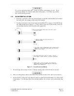
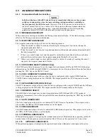
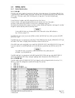
4.2
POWER, LIGHTING, AND ANTENNAS
4.2.1 Power, Lighting, and Antennas Function
The section covers the Power Input requirements, Lighting Bus input, and Antenna connections.
4.2.2 Power, Lighting, and Antennas Electrical Characteristics
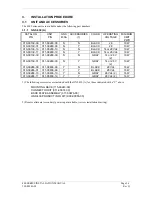
4.2.2.1 Aircraft Power
Pin Name
Connector
Pin
I/O
AIRCRAFT POWER 1
P4001
19
In
AIRCRAFT POWER 1
P4001
20
In
AIRCRAFT POWER 2 *
P4001
15
In
AIRCRAFT POWER 2 *
P4001
72
In
AIRCRAFT POWER
P4002
11
In
AIRCRAFT POWER
P4002
12
In
AIRCRAFT POWER
P4006
44
In
AIRCRAFT GROUND
P4001
77
--
AIRCRAFT GROUND
P4001
78
--
AIRCRAFT GROUND
P4002
21
--
AIRCRAFT GROUND
P4002
22
--
AIRCRAFT GROUND
P4006
41
--
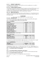
* Optional alternate power, applies only to part numbers 011-00280-30 GNS 430, 011-00836-10 GNS 430(A, 011-
00506-30 GNC 430, 011-00837-10 GNC 420(A), and 011-00504-10 (GPS 400).
CAUTION
To operate the GNC 420 P/N 011-00506-00 or GNS 430 P/N 011-00280-00 COM
transceiver in a 14-volt aircraft, a 14 to 28 volt converter such as a KGS Electronics
models RB-126 or UC-14-28 or equivalent must be used. The voltage converter should
include a circuit breaker on its output to supply power to P4002-11 and P4002-12 for the
COM transmitter. The other power input pins (P4001-19, P4001-20, and P4006-44)
accept 11-33 V
DC
. GNC 420 P/N 011-00506-10 and GNS 430 P/N 011-00280-10 accept
11-33 V
DC
on all power inputs. Refer to Figure F-13 on page F-27.
A power connection on P4006-44 is only required if NAV SUPERFLAG and/or G/S SUPERFLAG is
utilized.
The power inputs P4001-19 and P4001-20 provide power for all functions of the 400 Series unit except the
COM transmitter and the NAV & G/S SUPERFLAG outputs.
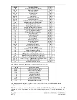
4.2.2.2 Lighting Bus
Pin Name
Connector
Pin
I/O
LIGHTING BUS HI
P4001
39
In
LIGHTING BUS LO
P4001
40
In
The 400 Series unit can be configured to track 28 V
DC
, 14 V
DC
, 5 V
DC
or 5 V
AC
lighting buses using these
inputs. Alternatively, the 400 Series unit can automatically adjust for ambient lighting conditions based on
the photocell. Refer to section 5.2.5.
4.2.2.3 Antennas
Pin Name
Connector
I/O
GPS ANTENNA
P4003
In
COM ANTENNA
P4004
I/O
VOR/LOC ANTENNA
P4005
In
GLIDESLOPE ANTENNA
P4007
In
Содержание GNC 420
Страница 8: ...Page vi 400 SERIES INSTALLATION MANUAL Rev Q 190 00140 02 This page intentionally left blank ...
Страница 28: ...Page 3 8 400 SERIES INSTALLATION MANUAL Rev Q 190 00140 02 This page intentionally left blank ...
Страница 78: ...Page A 8 400 SERIES INSTALLATION MANUAL Rev Q 190 00140 02 This page intentionally left blank ...
Страница 80: ...Page B 2 400 SERIES INSTALLATION MANUAL Rev Q 190 00140 02 ...
Страница 81: ...400 SERIES INSTALLATION MANUAL Page B 3 190 00140 02 Rev Q ...
Страница 82: ...Page B 4 400 SERIES INSTALLATION MANUAL Rev Q 190 00140 02 ...
Страница 83: ...400 SERIES INSTALLATION MANUAL Page B 5 190 00140 02 Rev Q ...
Страница 84: ...Page B 6 400 SERIES INSTALLATION MANUAL Rev Q 190 00140 02 ...
Страница 85: ...400 SERIES INSTALLATION MANUAL Page B 7 190 00140 02 Rev Q ...
Страница 86: ...Page B 8 400 SERIES INSTALLATION MANUAL Rev Q 190 00140 02 ...
Страница 87: ...400 SERIES INSTALLATION MANUAL Page B 9 190 00140 02 Rev Q ...
Страница 88: ...Page B 10 400 SERIES INSTALLATION MANUAL Rev Q 190 00140 02 This page intentionally left blank ...
Страница 103: ...400 SERIES INSTALLATION MANUAL Page F 3 Page F 4 blank 190 00140 02 Rev Q Figure F 1 GA 56 Antenna Installation Drawing ...
Страница 104: ...400 SERIES INSTALLATION MANUAL Page F 5 Page F 6 blank 190 00140 02 Rev Q Figure F 2 GNS 430 Mounting Rack Dimensions ...
Страница 105: ...400 SERIES INSTALLATION MANUAL Page F 7 Page F 8 blank 190 00140 02 Rev Q Figure F 3 GNC 420 Mounting Rack Dimensions ...
Страница 106: ...400 SERIES INSTALLATION MANUAL Page F 9 Page F 10 blank 190 00140 02 Rev Q Figure F 4 GPS 400 Mounting Rack Dimensions ...
Страница 112: ...400 SERIES INSTALLATION MANUAL Page F 21 Page F 22 blank 190 00140 02 Rev Q Figure F 10 GNS 430 Typical Installation ...
Страница 113: ...400 SERIES INSTALLATION MANUAL Page F 23 Page F 24 blank 190 00140 02 Rev Q Figure F 11 GNC 420 Typical Installation ...
Страница 114: ...400 SERIES INSTALLATION MANUAL Page F 25 Page F 26 blank 190 00140 02 Rev Q Figure F 12 GPS 400 Typical Installation ...
Страница 116: ...400 SERIES INSTALLATION MANUAL Page F 29 Page F 30 blank 190 00140 02 Rev Q Figure F 14 Altimeter Interconnect ...
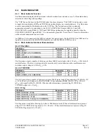
Страница 117: ...400 SERIES INSTALLATION MANUAL Page F 31 Page F 32 blank 190 00140 02 Rev Q Figure F 15 Main Indicator Interconnect ...
Страница 121: ...400 SERIES INSTALLATION MANUAL Page F 39 Page F 40 blank 190 00140 02 Rev Q Figure F 19 RS 232 Serial Data Interconnect ...
Страница 122: ...400 SERIES INSTALLATION MANUAL Page F 41 Page F 42 blank 190 00140 02 Rev Q Figure F 20 ARINC 429 EFIS Interconnect ...
Страница 130: ...400 SERIES INSTALLATION MANUAL Page F 57 Page F 58 blank 190 00140 02 Rev Q Figure F 28 Audio Panel Interconnect ...
Страница 131: ...400 SERIES INSTALLATION MANUAL Page F 59 Page F 60 blank 190 00140 02 Rev Q Figure F 29 VOR ILS Indicator Interconnect ...
Страница 132: ...400 SERIES INSTALLATION MANUAL Page F 61 Page F 62 blank 190 00140 02 Rev Q Figure F 30 RMI OBI Interconnect ...