


400 SERIES INSTALLATION MANUAL
Page 5-15
190-00140-02
Rev Q
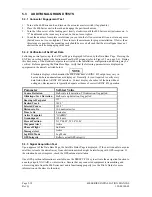
DME MODE
Selection Description
Directed freq 1
If the GNS 430 is connected to a multi-channel ARINC 429 DME, channel 1
of that DME is tuned. “Directed freq 1” should be selected if a single-
channel ARINC 429 DME is tuned.
Directed freq 2
If the GNS 430 is connected to a multi-channel ARINC 429 DME, channel 2
of that DME is tuned.
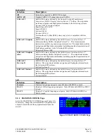
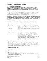
5.2.15 STORMSCOPE CONFIG Page
(Only if 400 Series unit is configured for BFG WX-500 Stormscope interface)
Select the STORMSCOPE CONFIG Page (see Figure 5-
19). This page shows the BF Goodrich WX-500
Stormscope configuration as reported by the WX-500
through RS-232 data.
Verify that the STATUS field indicates “Ok”, and that
the other displayed parameters are correct. Verify that all
the boxes in the lower portion of the page are green.
When a 400 Series unit is used with a WX-500
Stormscope, the “Synchro” or “Serial” heading formats
may be used. If another heading format is used,
lightning strike information is visible on the Weather Page, but not on the Map Page.
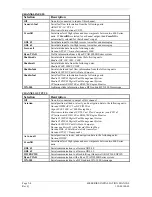
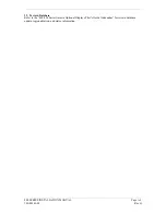
5.2.16 STORMSCOPE TEST Page
(Only if 400 Series unit is configured for BFG WX-500 Stormscope interface)
Select the STORMSCOPE TEST Page (see Figure 5-20).
This page shows current strike activity, WX-500 status,
and the heading supplied by the WX-500. The WX-500
mode may be changed to ‘Demo’, ‘Noise monitor’, ‘Self
test’, ‘Strike test’, or ‘Weather’.
Verify that the WX-500 mode can be changed. Refer to
the WX-500 manual for specific installation test
procedures for the WX-500, using this page to view strike
data, change the WX-500 mode, view WX-500 status,
trigger count, and heading.
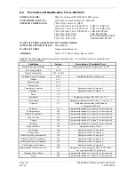
5.2.17 STORMSCOPE DOWNLOAD DATA Page
(Only if 400 Series unit is configured for BFG WX-500 Stormscope interface)
Select the STORMSCOPE TEST Page (see Figure 5-21).
This page shows raw data downloadable from the WX-
500. Optional sets of data include WX-500 software
version, environmental conditions, configuration, and fault
data.
Verify that the configuration data is correct as intended.
To request which packet of data to display, highlight the
data group title and use the small right knob to select the
desired group.
Figure 5-19.
STORMSCOPE CONFIG Page
Figure 5-20.
STORMSCOPE TEST Page
Figure 5-21. STORMSCOPE
DOWNLOAD DATA Page
Содержание GNC 420
Страница 8: ...Page vi 400 SERIES INSTALLATION MANUAL Rev Q 190 00140 02 This page intentionally left blank ...
Страница 28: ...Page 3 8 400 SERIES INSTALLATION MANUAL Rev Q 190 00140 02 This page intentionally left blank ...
Страница 78: ...Page A 8 400 SERIES INSTALLATION MANUAL Rev Q 190 00140 02 This page intentionally left blank ...
Страница 80: ...Page B 2 400 SERIES INSTALLATION MANUAL Rev Q 190 00140 02 ...
Страница 81: ...400 SERIES INSTALLATION MANUAL Page B 3 190 00140 02 Rev Q ...
Страница 82: ...Page B 4 400 SERIES INSTALLATION MANUAL Rev Q 190 00140 02 ...
Страница 83: ...400 SERIES INSTALLATION MANUAL Page B 5 190 00140 02 Rev Q ...
Страница 84: ...Page B 6 400 SERIES INSTALLATION MANUAL Rev Q 190 00140 02 ...
Страница 85: ...400 SERIES INSTALLATION MANUAL Page B 7 190 00140 02 Rev Q ...
Страница 86: ...Page B 8 400 SERIES INSTALLATION MANUAL Rev Q 190 00140 02 ...
Страница 87: ...400 SERIES INSTALLATION MANUAL Page B 9 190 00140 02 Rev Q ...
Страница 88: ...Page B 10 400 SERIES INSTALLATION MANUAL Rev Q 190 00140 02 This page intentionally left blank ...
Страница 103: ...400 SERIES INSTALLATION MANUAL Page F 3 Page F 4 blank 190 00140 02 Rev Q Figure F 1 GA 56 Antenna Installation Drawing ...
Страница 104: ...400 SERIES INSTALLATION MANUAL Page F 5 Page F 6 blank 190 00140 02 Rev Q Figure F 2 GNS 430 Mounting Rack Dimensions ...
Страница 105: ...400 SERIES INSTALLATION MANUAL Page F 7 Page F 8 blank 190 00140 02 Rev Q Figure F 3 GNC 420 Mounting Rack Dimensions ...
Страница 106: ...400 SERIES INSTALLATION MANUAL Page F 9 Page F 10 blank 190 00140 02 Rev Q Figure F 4 GPS 400 Mounting Rack Dimensions ...
Страница 112: ...400 SERIES INSTALLATION MANUAL Page F 21 Page F 22 blank 190 00140 02 Rev Q Figure F 10 GNS 430 Typical Installation ...
Страница 113: ...400 SERIES INSTALLATION MANUAL Page F 23 Page F 24 blank 190 00140 02 Rev Q Figure F 11 GNC 420 Typical Installation ...
Страница 114: ...400 SERIES INSTALLATION MANUAL Page F 25 Page F 26 blank 190 00140 02 Rev Q Figure F 12 GPS 400 Typical Installation ...
Страница 116: ...400 SERIES INSTALLATION MANUAL Page F 29 Page F 30 blank 190 00140 02 Rev Q Figure F 14 Altimeter Interconnect ...
Страница 117: ...400 SERIES INSTALLATION MANUAL Page F 31 Page F 32 blank 190 00140 02 Rev Q Figure F 15 Main Indicator Interconnect ...
Страница 121: ...400 SERIES INSTALLATION MANUAL Page F 39 Page F 40 blank 190 00140 02 Rev Q Figure F 19 RS 232 Serial Data Interconnect ...
Страница 122: ...400 SERIES INSTALLATION MANUAL Page F 41 Page F 42 blank 190 00140 02 Rev Q Figure F 20 ARINC 429 EFIS Interconnect ...
Страница 130: ...400 SERIES INSTALLATION MANUAL Page F 57 Page F 58 blank 190 00140 02 Rev Q Figure F 28 Audio Panel Interconnect ...
Страница 131: ...400 SERIES INSTALLATION MANUAL Page F 59 Page F 60 blank 190 00140 02 Rev Q Figure F 29 VOR ILS Indicator Interconnect ...
Страница 132: ...400 SERIES INSTALLATION MANUAL Page F 61 Page F 62 blank 190 00140 02 Rev Q Figure F 30 RMI OBI Interconnect ...