


400 SERIES INSTALLATION MANUAL
Page 5-1
190-00140-02
Rev Q
5.
POST INSTALLATION CONFIGURATION & CHECKOUT PROCEDURE
5.1
CONFIGURATION MODE OPERATIONS
With power applied to the aviation rack and the 400 Series unit turned off, press and hold the ENT key and
turn the unit on. Release the ENT key when the display activates. The unit is now in configuration mode.
After the database pages, the first page displayed is the MAIN ARINC 429 CONFIG page. While in
configuration mode, pages can be selected by ensuring the cursor is off and rotating the small right knob.
To change data on the displayed configuration pages, press the small right knob (CRSR) to turn on the
cursor. Turn the large right knob to change between data fields. Turn the large or small right knob to
change a field that the cursor is on. Once you have made the desired selection, press the ENT key to
accept the entry.
5.2
INSTALLATION CONFIGURATION PAGES
The configuration pages described in the following sections are in the order found when rotating the right
small knob clockwise starting at the MAIN ARINC 429 CONFIG page. Use the procedure described in
section 5.1 to get to this page.
NOTE
The configuration pages shown here reflect MAIN software version 5.01. All
configuration pages shown apply to the GNS 430, but not all apply to the GPS 400 or
GNC 420. Those pages and fields that apply only to certain 400 Series units are denoted
as such.
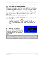
5.2.1 MAIN ARINC 429 CONFIG Page
Select the MAIN ARINC 429 CONFIG Page (see Figure
5-1). This page configures the GPS ARINC 429 output
port, and the two GPS ARINC 429 input ports. The two
input ports can each be configured independently for the
desired function(s).
SPEED
Selection Description
Low
Standard low-speed ARINC 429 (nominally 12.5 kilobits per second)
High
High-speed ARINC 429 (nominally 100 kilobits per second)
Figure 5-1.
MAIN ARINC 429 CONFIG Page
Содержание GNC 420
Страница 8: ...Page vi 400 SERIES INSTALLATION MANUAL Rev Q 190 00140 02 This page intentionally left blank ...
Страница 28: ...Page 3 8 400 SERIES INSTALLATION MANUAL Rev Q 190 00140 02 This page intentionally left blank ...
Страница 78: ...Page A 8 400 SERIES INSTALLATION MANUAL Rev Q 190 00140 02 This page intentionally left blank ...
Страница 80: ...Page B 2 400 SERIES INSTALLATION MANUAL Rev Q 190 00140 02 ...
Страница 81: ...400 SERIES INSTALLATION MANUAL Page B 3 190 00140 02 Rev Q ...
Страница 82: ...Page B 4 400 SERIES INSTALLATION MANUAL Rev Q 190 00140 02 ...
Страница 83: ...400 SERIES INSTALLATION MANUAL Page B 5 190 00140 02 Rev Q ...
Страница 84: ...Page B 6 400 SERIES INSTALLATION MANUAL Rev Q 190 00140 02 ...
Страница 85: ...400 SERIES INSTALLATION MANUAL Page B 7 190 00140 02 Rev Q ...
Страница 86: ...Page B 8 400 SERIES INSTALLATION MANUAL Rev Q 190 00140 02 ...
Страница 87: ...400 SERIES INSTALLATION MANUAL Page B 9 190 00140 02 Rev Q ...
Страница 88: ...Page B 10 400 SERIES INSTALLATION MANUAL Rev Q 190 00140 02 This page intentionally left blank ...
Страница 103: ...400 SERIES INSTALLATION MANUAL Page F 3 Page F 4 blank 190 00140 02 Rev Q Figure F 1 GA 56 Antenna Installation Drawing ...
Страница 104: ...400 SERIES INSTALLATION MANUAL Page F 5 Page F 6 blank 190 00140 02 Rev Q Figure F 2 GNS 430 Mounting Rack Dimensions ...
Страница 105: ...400 SERIES INSTALLATION MANUAL Page F 7 Page F 8 blank 190 00140 02 Rev Q Figure F 3 GNC 420 Mounting Rack Dimensions ...
Страница 106: ...400 SERIES INSTALLATION MANUAL Page F 9 Page F 10 blank 190 00140 02 Rev Q Figure F 4 GPS 400 Mounting Rack Dimensions ...
Страница 112: ...400 SERIES INSTALLATION MANUAL Page F 21 Page F 22 blank 190 00140 02 Rev Q Figure F 10 GNS 430 Typical Installation ...
Страница 113: ...400 SERIES INSTALLATION MANUAL Page F 23 Page F 24 blank 190 00140 02 Rev Q Figure F 11 GNC 420 Typical Installation ...
Страница 114: ...400 SERIES INSTALLATION MANUAL Page F 25 Page F 26 blank 190 00140 02 Rev Q Figure F 12 GPS 400 Typical Installation ...
Страница 116: ...400 SERIES INSTALLATION MANUAL Page F 29 Page F 30 blank 190 00140 02 Rev Q Figure F 14 Altimeter Interconnect ...
Страница 117: ...400 SERIES INSTALLATION MANUAL Page F 31 Page F 32 blank 190 00140 02 Rev Q Figure F 15 Main Indicator Interconnect ...
Страница 121: ...400 SERIES INSTALLATION MANUAL Page F 39 Page F 40 blank 190 00140 02 Rev Q Figure F 19 RS 232 Serial Data Interconnect ...
Страница 122: ...400 SERIES INSTALLATION MANUAL Page F 41 Page F 42 blank 190 00140 02 Rev Q Figure F 20 ARINC 429 EFIS Interconnect ...
Страница 130: ...400 SERIES INSTALLATION MANUAL Page F 57 Page F 58 blank 190 00140 02 Rev Q Figure F 28 Audio Panel Interconnect ...
Страница 131: ...400 SERIES INSTALLATION MANUAL Page F 59 Page F 60 blank 190 00140 02 Rev Q Figure F 29 VOR ILS Indicator Interconnect ...
Страница 132: ...400 SERIES INSTALLATION MANUAL Page F 61 Page F 62 blank 190 00140 02 Rev Q Figure F 30 RMI OBI Interconnect ...


