


400 SERIES INSTALLATION MANUAL
Page 4-9
190-00140-02
Rev
Q
4.5 ANNUNCIATORS/SWITCHES
4.5.1 Annunciators/Switches
Function
NOTE
Initial certification of the 400 Series units was accomplished without use of any remote
switches or annunciators, since the same switching and annunciation is available on
the front panel of the 400 Series unit.
However, if the 400 Series unit is not installed in
the pilot’s normal field of view, some or all of the remote switches and annunciators may
be required by your certification agency. Appendix B includes an FAA letter granting
permission to install GNS 430 without external switches and annunciators.
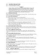
4.5.1.1 MESSAGE ANNUNCIATE
When a new status message is available, the Message Annunciator flashes. When status messages remain
effective, the Message Annunciator illuminates.
4.5.1.2 WAYPOINT ANNUNCIATE
The waypoint annunciator output is driven in the following manner:
1. When the aircraft is within 10 seconds of reaching the turning point for a course change, the
waypoint annunciator flashes.
2. When the aircraft is in a turn, the waypoint annunciator illuminates and remains illuminated until
the turn is completed.
3. When a user arrival alarm is set and the aircraft is within the circle defined by the arrival alarm
radius at the arrival waypoint, the waypoint annunciator flashes for 10 seconds.
4. When a user arrival alarm is not set and the aircraft is within 10 seconds of reaching the arrival
waypoint, the waypoint annunciator flashes.
4.5.1.3 CDI SOURCE SELECT (GNS 430 Only)
This CDI Source Select input may be used to toggle between display of GPS and VOR/LOC/Glideslope
information on the MAIN external CDI/HSI. A momentary low on this pin performs the same function as
pressing the ‘CDI’ key on the GNS 430 bezel.
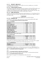
4.5.1.4 VLOC ANNUNCIATE (GNS 430 Only)
This VLOC Annunciate output is driven when the unit is configured with a single CDI/HSI and the
VOR/ILS data is being displayed on the CDI/HSI. This output parallels the VLOC annunciator on the
display.
4.5.1.5 GPS ANNUNCIATE (GNS 430 Only)
This GPS Annunciate output is driven when the unit is configured with a single CDI/HSI and the GPS data
is being displayed on the CDI/HSI. This output parallels the GPS annunciation on the display.
4.5.1.6 OBS MODE SELECT
This OBS Mode Select input may be used to toggle between GPS OBS and GPS AUTO modes of
operation. A momentary low on this pin performs the same function as pressing the ‘OBS’ key on the 400
Series unit.
4.5.1.7 AUTO ANNUNCIATE
This Auto Annunciate output is driven to indicate GPS AUTO mode of operation. This output is active
when neither the OBS nor SUSP annunciations are on the display.
4.5.1.8 OBS ANNUNCIATE
This OBS Annunciate output is driven to indicate GPS OBS mode of operation. This output is active when
the OBS or SUSP annunciation is on the display.
4.5.1.9 TERMINAL ANNUNCIATE
When performing approach navigation, the terminal annunciator is illuminated when operating within 30
nautical miles of the departure or arrival airport and the CDI scale is the equivalent or 1.0 nm or less.
4.5.1.10 APPROACH
ANNUNCIATE
When performing approach navigation, the approach annunciator illuminates when approach is active.
Содержание GNC 420
Страница 8: ...Page vi 400 SERIES INSTALLATION MANUAL Rev Q 190 00140 02 This page intentionally left blank ...
Страница 28: ...Page 3 8 400 SERIES INSTALLATION MANUAL Rev Q 190 00140 02 This page intentionally left blank ...
Страница 78: ...Page A 8 400 SERIES INSTALLATION MANUAL Rev Q 190 00140 02 This page intentionally left blank ...
Страница 80: ...Page B 2 400 SERIES INSTALLATION MANUAL Rev Q 190 00140 02 ...
Страница 81: ...400 SERIES INSTALLATION MANUAL Page B 3 190 00140 02 Rev Q ...
Страница 82: ...Page B 4 400 SERIES INSTALLATION MANUAL Rev Q 190 00140 02 ...
Страница 83: ...400 SERIES INSTALLATION MANUAL Page B 5 190 00140 02 Rev Q ...
Страница 84: ...Page B 6 400 SERIES INSTALLATION MANUAL Rev Q 190 00140 02 ...
Страница 85: ...400 SERIES INSTALLATION MANUAL Page B 7 190 00140 02 Rev Q ...
Страница 86: ...Page B 8 400 SERIES INSTALLATION MANUAL Rev Q 190 00140 02 ...
Страница 87: ...400 SERIES INSTALLATION MANUAL Page B 9 190 00140 02 Rev Q ...
Страница 88: ...Page B 10 400 SERIES INSTALLATION MANUAL Rev Q 190 00140 02 This page intentionally left blank ...
Страница 103: ...400 SERIES INSTALLATION MANUAL Page F 3 Page F 4 blank 190 00140 02 Rev Q Figure F 1 GA 56 Antenna Installation Drawing ...
Страница 104: ...400 SERIES INSTALLATION MANUAL Page F 5 Page F 6 blank 190 00140 02 Rev Q Figure F 2 GNS 430 Mounting Rack Dimensions ...
Страница 105: ...400 SERIES INSTALLATION MANUAL Page F 7 Page F 8 blank 190 00140 02 Rev Q Figure F 3 GNC 420 Mounting Rack Dimensions ...
Страница 106: ...400 SERIES INSTALLATION MANUAL Page F 9 Page F 10 blank 190 00140 02 Rev Q Figure F 4 GPS 400 Mounting Rack Dimensions ...
Страница 112: ...400 SERIES INSTALLATION MANUAL Page F 21 Page F 22 blank 190 00140 02 Rev Q Figure F 10 GNS 430 Typical Installation ...
Страница 113: ...400 SERIES INSTALLATION MANUAL Page F 23 Page F 24 blank 190 00140 02 Rev Q Figure F 11 GNC 420 Typical Installation ...
Страница 114: ...400 SERIES INSTALLATION MANUAL Page F 25 Page F 26 blank 190 00140 02 Rev Q Figure F 12 GPS 400 Typical Installation ...
Страница 116: ...400 SERIES INSTALLATION MANUAL Page F 29 Page F 30 blank 190 00140 02 Rev Q Figure F 14 Altimeter Interconnect ...
Страница 117: ...400 SERIES INSTALLATION MANUAL Page F 31 Page F 32 blank 190 00140 02 Rev Q Figure F 15 Main Indicator Interconnect ...
Страница 121: ...400 SERIES INSTALLATION MANUAL Page F 39 Page F 40 blank 190 00140 02 Rev Q Figure F 19 RS 232 Serial Data Interconnect ...
Страница 122: ...400 SERIES INSTALLATION MANUAL Page F 41 Page F 42 blank 190 00140 02 Rev Q Figure F 20 ARINC 429 EFIS Interconnect ...
Страница 130: ...400 SERIES INSTALLATION MANUAL Page F 57 Page F 58 blank 190 00140 02 Rev Q Figure F 28 Audio Panel Interconnect ...
Страница 131: ...400 SERIES INSTALLATION MANUAL Page F 59 Page F 60 blank 190 00140 02 Rev Q Figure F 29 VOR ILS Indicator Interconnect ...
Страница 132: ...400 SERIES INSTALLATION MANUAL Page F 61 Page F 62 blank 190 00140 02 Rev Q Figure F 30 RMI OBI Interconnect ...