400 SERIES INSTALLATION MANUAL
Page 1-7
190-00140-02
Rev
Q
1.4 TSO
LIMITATIONS
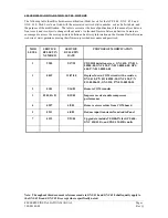
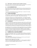
A limitation exists pertaining to TSO-C36e (Localizer) and TSO-C34e (Glideslope). The main board
lateral deviation (J4001 Pin 21 MAIN +LEFT and J4001 Pin 22 MAIN +RIGHT) and vertical deviation
(J4001 Pin 27 MAIN +UP and J4001 Pin 28 MAIN +DOWN) outputs exceed the respective TSO MOPS
requirement for current response time due to 120 milliseconds of internal transport delay. Except for this
transport delay, the output characteristics meet the TSO MOPS requirement. Consequently, these outputs
should be used only in applications where the transport delay has been evaluated and found to meet
installation requirements.
1.5 LICENSE
REQUIREMENTS
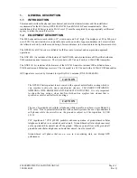
The Telecommunications Act of 1996, effective February 8, 1996, provides the FCC discretion to eliminate
radio station license requirements for aircraft and ships. The 400 Series unit installation must comply with
current transmitter licensing requirements. To find out the specific details on whether a particular
installation is exempt from licensing, please visit the FCC web site
http://wireless.fcc.gov/aviation
.
If an aircraft license is required, make application for a license on FCC form 404, Application for Aircraft
Radio Station License. The FCC also has a fax-on-demand service to provide forms by fax. The 400
Series unit owner accepts all responsibility for obtaining the proper licensing before using the transponder.
CAUTION
The VHF transmitter in this equipment is guaranteed to meet federal communications
commission acceptance over the operating temperature range. Modifications not
expressly approved by Garmin could invalidate the license and make it unlawful to
operate the equipment.
1.6 CERTIFICATION
The GPS receivers in the 400 Series units are certified for IFR enroute, terminal, and non-precision
approaches. The 400 Series initial certification was accomplished via STC’s by Garmin in a Piper PA32.
See Appendix B for copies of the STC’s.
The 400 Series units have been qualified to RTCA/DO-160 Section 22 lightning requirements. Special
installation considerations are required, refer to the Environmental Qualification Forms in Appendix A.
1.7
FAULT DETECTION AND EXCLUSION (FDE)
NOTE
The 400 Series equipment as installed has been found to comply with the requirements
for GPS primary means of navigation in oceanic and remote airspace, when used in
conjunction with the 400 Series Trainer Program incorporating the FDE Prediction
Program. This does not constitute an operational approval.
The Garmin 400 Series Main and GPS Software version 3.00 and higher incorporate Fault Detection and
Exclusion (FDE) display interface and control, satisfying the requirements for GPS as a Primary Means of
Navigation for Oceanic/Remote Operations per FAA Notice N8110.60.
Fault Detection and Exclusion consists of two parts. The fault detection function detects a satellite failure
that can affect navigation. The exclusion function refers to the capability of excluding one or more failed
satellites and preventing them from affecting navigation.
Содержание GNC 420
Страница 8: ...Page vi 400 SERIES INSTALLATION MANUAL Rev Q 190 00140 02 This page intentionally left blank ...
Страница 28: ...Page 3 8 400 SERIES INSTALLATION MANUAL Rev Q 190 00140 02 This page intentionally left blank ...
Страница 78: ...Page A 8 400 SERIES INSTALLATION MANUAL Rev Q 190 00140 02 This page intentionally left blank ...
Страница 80: ...Page B 2 400 SERIES INSTALLATION MANUAL Rev Q 190 00140 02 ...
Страница 81: ...400 SERIES INSTALLATION MANUAL Page B 3 190 00140 02 Rev Q ...
Страница 82: ...Page B 4 400 SERIES INSTALLATION MANUAL Rev Q 190 00140 02 ...
Страница 83: ...400 SERIES INSTALLATION MANUAL Page B 5 190 00140 02 Rev Q ...
Страница 84: ...Page B 6 400 SERIES INSTALLATION MANUAL Rev Q 190 00140 02 ...
Страница 85: ...400 SERIES INSTALLATION MANUAL Page B 7 190 00140 02 Rev Q ...
Страница 86: ...Page B 8 400 SERIES INSTALLATION MANUAL Rev Q 190 00140 02 ...
Страница 87: ...400 SERIES INSTALLATION MANUAL Page B 9 190 00140 02 Rev Q ...
Страница 88: ...Page B 10 400 SERIES INSTALLATION MANUAL Rev Q 190 00140 02 This page intentionally left blank ...
Страница 103: ...400 SERIES INSTALLATION MANUAL Page F 3 Page F 4 blank 190 00140 02 Rev Q Figure F 1 GA 56 Antenna Installation Drawing ...
Страница 104: ...400 SERIES INSTALLATION MANUAL Page F 5 Page F 6 blank 190 00140 02 Rev Q Figure F 2 GNS 430 Mounting Rack Dimensions ...
Страница 105: ...400 SERIES INSTALLATION MANUAL Page F 7 Page F 8 blank 190 00140 02 Rev Q Figure F 3 GNC 420 Mounting Rack Dimensions ...
Страница 106: ...400 SERIES INSTALLATION MANUAL Page F 9 Page F 10 blank 190 00140 02 Rev Q Figure F 4 GPS 400 Mounting Rack Dimensions ...
Страница 112: ...400 SERIES INSTALLATION MANUAL Page F 21 Page F 22 blank 190 00140 02 Rev Q Figure F 10 GNS 430 Typical Installation ...
Страница 113: ...400 SERIES INSTALLATION MANUAL Page F 23 Page F 24 blank 190 00140 02 Rev Q Figure F 11 GNC 420 Typical Installation ...
Страница 114: ...400 SERIES INSTALLATION MANUAL Page F 25 Page F 26 blank 190 00140 02 Rev Q Figure F 12 GPS 400 Typical Installation ...
Страница 116: ...400 SERIES INSTALLATION MANUAL Page F 29 Page F 30 blank 190 00140 02 Rev Q Figure F 14 Altimeter Interconnect ...
Страница 117: ...400 SERIES INSTALLATION MANUAL Page F 31 Page F 32 blank 190 00140 02 Rev Q Figure F 15 Main Indicator Interconnect ...
Страница 121: ...400 SERIES INSTALLATION MANUAL Page F 39 Page F 40 blank 190 00140 02 Rev Q Figure F 19 RS 232 Serial Data Interconnect ...
Страница 122: ...400 SERIES INSTALLATION MANUAL Page F 41 Page F 42 blank 190 00140 02 Rev Q Figure F 20 ARINC 429 EFIS Interconnect ...
Страница 130: ...400 SERIES INSTALLATION MANUAL Page F 57 Page F 58 blank 190 00140 02 Rev Q Figure F 28 Audio Panel Interconnect ...
Страница 131: ...400 SERIES INSTALLATION MANUAL Page F 59 Page F 60 blank 190 00140 02 Rev Q Figure F 29 VOR ILS Indicator Interconnect ...
Страница 132: ...400 SERIES INSTALLATION MANUAL Page F 61 Page F 62 blank 190 00140 02 Rev Q Figure F 30 RMI OBI Interconnect ...


