


Page 4-4
400 SERIES INSTALLATION MANUAL
Rev Q
190-00140-02
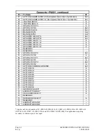
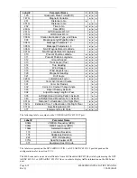
4.1.3 P4006 (GNS 430 Only)
View of J4006 connector from back of unit
1
2
3
4
5
6
7
8
9
10
11
12
13
14
15
16
17
18
19
20
21
22
23
24
25
26
27
28
29
30
31
32
33
34
35
36
37
38
39
40
41
42
43
44
Pin Pin
Name
I/O
1 VOR/LOC
+TO
Out
2
VOR/LOC +FROM (VOR/LOC COMMON)
Out
3 VOR/LOC
+FLAG
Out
4
VOR/LOC -FLAG (VOR/LOC COMMON)
Out
5 VOR/LOC
+LEFT
Out
6
VOR/LOC +RIGHT (VOR/LOC COMMON)
Out
7 RESERVED
--
8
VOR/LOC COMPOSITE OUT
Out
9
VOR OBS ROTOR C
Out
10
VOR OBS ROTOR H (GROUND)
Out
11
VOR OBS STATOR E/G (VOR/LOC COMMON)
In
12
VOR OBS STATOR F
In
13
VOR OBS STATOR D
In
14
PARALLEL DME - 8MHZ
Out
15 VOR/LOC
SUPERFLAG
Out
16
500
:
VOR/ILS AUDIO HI
Out
17
500
:
VOR/ILS AUDIO LO
Out
18
SERIAL DME CLOCK
Out
19
SERIAL DME DATA
Out
20
SER DME - CHAN REQ/PAR DME - 4MHZ
I/O
21
SER DME - RNAV MODE/PAR DME - 2MHZ
I/O
22 DME
COMMON
In
23
VOR/ILS ARINC 429 OUT B
Out
24
VOR/ILS ARINC 429 OUT A
Out
25
VOR OBI CLOCK
Out
26
VOR OBI SYNC
Out
27
VOR OBI DATA
Out
28
VLOC REMOTE TRANSFER
In
29 ILS
ENERGIZE
Out
30 GLIDESLOPE
+FLAG
Out
31
GLIDDOWN/-FLAG (GLIDESLOPE COMMON)
Out
32 GLIDESLOPE
+UP
Out
33
PARALLEL DME - 1MHZ
Out
34 RESERVED
--
35
VOR/ILS ARINC 429 IN B
In
36
VOR/ILS ARINC 429 IN A
In
37
PARALLEL DME - 800KHZ
Out
38 GLIDESLOPE
SUPERFLAG
Out
39
PARALLEL DME - 400KHZ
Out
40
PARALLEL DME - 200KHZ
Out
41 AIRCRAFT
GROUND
--
42
PARALLEL DME - 100KHZ
Out
43
PARALLEL DME - 50KHZ
Out
44 AIRCRAFT
POWER
In
Содержание GNC 420
Страница 8: ...Page vi 400 SERIES INSTALLATION MANUAL Rev Q 190 00140 02 This page intentionally left blank ...
Страница 28: ...Page 3 8 400 SERIES INSTALLATION MANUAL Rev Q 190 00140 02 This page intentionally left blank ...
Страница 78: ...Page A 8 400 SERIES INSTALLATION MANUAL Rev Q 190 00140 02 This page intentionally left blank ...
Страница 80: ...Page B 2 400 SERIES INSTALLATION MANUAL Rev Q 190 00140 02 ...
Страница 81: ...400 SERIES INSTALLATION MANUAL Page B 3 190 00140 02 Rev Q ...
Страница 82: ...Page B 4 400 SERIES INSTALLATION MANUAL Rev Q 190 00140 02 ...
Страница 83: ...400 SERIES INSTALLATION MANUAL Page B 5 190 00140 02 Rev Q ...
Страница 84: ...Page B 6 400 SERIES INSTALLATION MANUAL Rev Q 190 00140 02 ...
Страница 85: ...400 SERIES INSTALLATION MANUAL Page B 7 190 00140 02 Rev Q ...
Страница 86: ...Page B 8 400 SERIES INSTALLATION MANUAL Rev Q 190 00140 02 ...
Страница 87: ...400 SERIES INSTALLATION MANUAL Page B 9 190 00140 02 Rev Q ...
Страница 88: ...Page B 10 400 SERIES INSTALLATION MANUAL Rev Q 190 00140 02 This page intentionally left blank ...
Страница 103: ...400 SERIES INSTALLATION MANUAL Page F 3 Page F 4 blank 190 00140 02 Rev Q Figure F 1 GA 56 Antenna Installation Drawing ...
Страница 104: ...400 SERIES INSTALLATION MANUAL Page F 5 Page F 6 blank 190 00140 02 Rev Q Figure F 2 GNS 430 Mounting Rack Dimensions ...
Страница 105: ...400 SERIES INSTALLATION MANUAL Page F 7 Page F 8 blank 190 00140 02 Rev Q Figure F 3 GNC 420 Mounting Rack Dimensions ...
Страница 106: ...400 SERIES INSTALLATION MANUAL Page F 9 Page F 10 blank 190 00140 02 Rev Q Figure F 4 GPS 400 Mounting Rack Dimensions ...
Страница 112: ...400 SERIES INSTALLATION MANUAL Page F 21 Page F 22 blank 190 00140 02 Rev Q Figure F 10 GNS 430 Typical Installation ...
Страница 113: ...400 SERIES INSTALLATION MANUAL Page F 23 Page F 24 blank 190 00140 02 Rev Q Figure F 11 GNC 420 Typical Installation ...
Страница 114: ...400 SERIES INSTALLATION MANUAL Page F 25 Page F 26 blank 190 00140 02 Rev Q Figure F 12 GPS 400 Typical Installation ...
Страница 116: ...400 SERIES INSTALLATION MANUAL Page F 29 Page F 30 blank 190 00140 02 Rev Q Figure F 14 Altimeter Interconnect ...
Страница 117: ...400 SERIES INSTALLATION MANUAL Page F 31 Page F 32 blank 190 00140 02 Rev Q Figure F 15 Main Indicator Interconnect ...
Страница 121: ...400 SERIES INSTALLATION MANUAL Page F 39 Page F 40 blank 190 00140 02 Rev Q Figure F 19 RS 232 Serial Data Interconnect ...
Страница 122: ...400 SERIES INSTALLATION MANUAL Page F 41 Page F 42 blank 190 00140 02 Rev Q Figure F 20 ARINC 429 EFIS Interconnect ...
Страница 130: ...400 SERIES INSTALLATION MANUAL Page F 57 Page F 58 blank 190 00140 02 Rev Q Figure F 28 Audio Panel Interconnect ...
Страница 131: ...400 SERIES INSTALLATION MANUAL Page F 59 Page F 60 blank 190 00140 02 Rev Q Figure F 29 VOR ILS Indicator Interconnect ...
Страница 132: ...400 SERIES INSTALLATION MANUAL Page F 61 Page F 62 blank 190 00140 02 Rev Q Figure F 30 RMI OBI Interconnect ...