


400 SERIES INSTALLATION MANUAL
Page 4-19
190-00140-02
Rev
Q
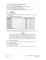
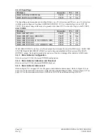
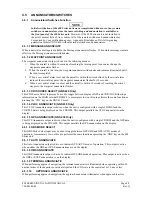
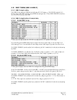
4.10 DME TUNING (GNS 430 ONLY)
4.10.1 DME Tuning Function
The GNS 430 can channel a DME based on the tuned VLOC frequency. The GNS 430 outputs 2 of 5,
BCD or Slip parallel DME and King Serial DME channeling format. When DME COMMON is held low,
the GNS 430 actively tunes the DME.
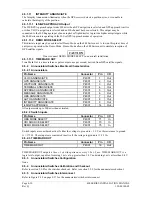
4.10.2 DME Tuning Electrical Characteristics
4.10.2.1 Parallel DME Tuning
Pin Name
Connector
Pin
I/O
NAV PAR DME - 8MHZ
P4006
14
Out
SER DME – CHAN REQ/PAR DME - 4MHZ
P4006
20
Out*
SER DME – RNAV MODE/PAR DME - 2MHZ
P4006
21
Out*
NAV PAR DME - 1MHZ
P4006
33
Out
NAV PAR DME - 800KHZ
P4006
37
Out
NAV PAR DME - 400KHZ
P4006
39
Out
NAV PAR DME - 200KHZ
P4006
40
Out
NAV PAR DME - 100KHZ
P4006
42
Out
NAV PAR DME - 50KHZ
P4006
43
Out
NAV DME COMMON
P4006
22
In
* These pins are outputs when the GNS 430 is configured for 2 of 5 parallel DME tuning.
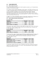
For each of the parallel DME tuning discrete outputs, the driver output voltage is not more than 1.0 V
while sinking 20 mA. The maximum off state leakage current with respect to ground is less than 10
P
A.
NAV DME COMMON must be pulled low to indicate to the NAV module that it is the device channeling
the DME.
NAV DME COMMON is considered active if either the voltage to ground is < 1.9 V or the resistance to
ground is< 375
:
. These inputs are considered inactive if the voltage to ground is 11-33 V
DC
.
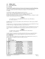
4.10.2.2 King Serial DME Tuning
Pin Name
Connector
Pin
I/O
NAV SER DME - DATA
P4006
19
Out
NAV SER DME - CLOCK
P4006
18
Out
SER DME – CHAN REQ/PAR DME - 4MHZ
P4006
20
In*
SER DME – RNAV MODE/PAR DME – 2MHZ
P4006
21
In*
NAV DME COMMON
P4006
22
In
* These pins are inputs when the GNS 430 is configured for King Serial DME tuning
When NAV SER DME – DATA or NAV SER DME – CLOCK is asserted high and driving a 360
:
load,
the driver output voltage is not less than 8 V, and when asserted low shall not be greater than 10 mV.
SER DME – CHAN REQ/PAR DME – 4MHZ, SER DME – RNAV MODE/PAR DME – 2MHz, and
NAV DME COMMON are considered active if either the voltage to ground is < 1.9 V or the resistance to
ground
is< 375
:
. These inputs are considered inactive if the voltage to ground is 11-33 V
DC
.
NAV DME COMMON must be pulled low to indicate to the NAV module that it is the device channeling
the DME.
Содержание GNC 420
Страница 8: ...Page vi 400 SERIES INSTALLATION MANUAL Rev Q 190 00140 02 This page intentionally left blank ...
Страница 28: ...Page 3 8 400 SERIES INSTALLATION MANUAL Rev Q 190 00140 02 This page intentionally left blank ...
Страница 78: ...Page A 8 400 SERIES INSTALLATION MANUAL Rev Q 190 00140 02 This page intentionally left blank ...
Страница 80: ...Page B 2 400 SERIES INSTALLATION MANUAL Rev Q 190 00140 02 ...
Страница 81: ...400 SERIES INSTALLATION MANUAL Page B 3 190 00140 02 Rev Q ...
Страница 82: ...Page B 4 400 SERIES INSTALLATION MANUAL Rev Q 190 00140 02 ...
Страница 83: ...400 SERIES INSTALLATION MANUAL Page B 5 190 00140 02 Rev Q ...
Страница 84: ...Page B 6 400 SERIES INSTALLATION MANUAL Rev Q 190 00140 02 ...
Страница 85: ...400 SERIES INSTALLATION MANUAL Page B 7 190 00140 02 Rev Q ...
Страница 86: ...Page B 8 400 SERIES INSTALLATION MANUAL Rev Q 190 00140 02 ...
Страница 87: ...400 SERIES INSTALLATION MANUAL Page B 9 190 00140 02 Rev Q ...
Страница 88: ...Page B 10 400 SERIES INSTALLATION MANUAL Rev Q 190 00140 02 This page intentionally left blank ...
Страница 103: ...400 SERIES INSTALLATION MANUAL Page F 3 Page F 4 blank 190 00140 02 Rev Q Figure F 1 GA 56 Antenna Installation Drawing ...
Страница 104: ...400 SERIES INSTALLATION MANUAL Page F 5 Page F 6 blank 190 00140 02 Rev Q Figure F 2 GNS 430 Mounting Rack Dimensions ...
Страница 105: ...400 SERIES INSTALLATION MANUAL Page F 7 Page F 8 blank 190 00140 02 Rev Q Figure F 3 GNC 420 Mounting Rack Dimensions ...
Страница 106: ...400 SERIES INSTALLATION MANUAL Page F 9 Page F 10 blank 190 00140 02 Rev Q Figure F 4 GPS 400 Mounting Rack Dimensions ...
Страница 112: ...400 SERIES INSTALLATION MANUAL Page F 21 Page F 22 blank 190 00140 02 Rev Q Figure F 10 GNS 430 Typical Installation ...
Страница 113: ...400 SERIES INSTALLATION MANUAL Page F 23 Page F 24 blank 190 00140 02 Rev Q Figure F 11 GNC 420 Typical Installation ...
Страница 114: ...400 SERIES INSTALLATION MANUAL Page F 25 Page F 26 blank 190 00140 02 Rev Q Figure F 12 GPS 400 Typical Installation ...
Страница 116: ...400 SERIES INSTALLATION MANUAL Page F 29 Page F 30 blank 190 00140 02 Rev Q Figure F 14 Altimeter Interconnect ...
Страница 117: ...400 SERIES INSTALLATION MANUAL Page F 31 Page F 32 blank 190 00140 02 Rev Q Figure F 15 Main Indicator Interconnect ...
Страница 121: ...400 SERIES INSTALLATION MANUAL Page F 39 Page F 40 blank 190 00140 02 Rev Q Figure F 19 RS 232 Serial Data Interconnect ...
Страница 122: ...400 SERIES INSTALLATION MANUAL Page F 41 Page F 42 blank 190 00140 02 Rev Q Figure F 20 ARINC 429 EFIS Interconnect ...
Страница 130: ...400 SERIES INSTALLATION MANUAL Page F 57 Page F 58 blank 190 00140 02 Rev Q Figure F 28 Audio Panel Interconnect ...
Страница 131: ...400 SERIES INSTALLATION MANUAL Page F 59 Page F 60 blank 190 00140 02 Rev Q Figure F 29 VOR ILS Indicator Interconnect ...
Страница 132: ...400 SERIES INSTALLATION MANUAL Page F 61 Page F 62 blank 190 00140 02 Rev Q Figure F 30 RMI OBI Interconnect ...