


Page 4-10
400 SERIES INSTALLATION MANUAL
Rev Q
190-00140-02
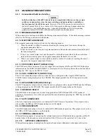
4.5.1.11 INTEGRITY
ANNUNCIATE
The Integrity Annunciator illuminates when the GPS receiver detects a position error, or is unable to
calculate the integrity of the position.
4.5.1.11.1 ILS/GPS APPROACH Output
The ILS/GPS Approach output sinks 500 mA when GPS navigation is selected and GPS approach is active
or when VLOC navigation is selected and an ILS channel has been selected. This output may be
connected to the ILS Engage input of an autopilot or flight director to provide higher autopilot gain while
the 400 Series unit is operating in the ILS or GPS Approach modes of operation.
4.5.1.11.2 DEMO MODE SELECT
This discrete input may be used to select Demo Mode on the 400 Series unit. A low on this pin at time of
unit power-up invokes the Demo Mode. Demo Mode allows the 400 Series unit to simulate reception of
GPS satellite signals.
CAUTION
Do not connect DEMO MODE SELECT in an aircraft installation.
4.5.1.11.3 TIME MARK OUT
Time Mark Out is a time reference pulse output once per second, derived from GPS satellite signals.
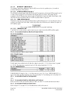
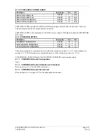
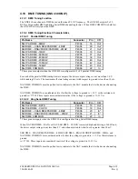
4.5.2 Annunciators/Switches Electrical Characteristics
4.5.2.1 Annunciators
Pin Name
Connector
Pin
I/O
VLOC ANNUNCIATE
P4001
1
Out
GPS ANNUNCIATE
P4001
2
Out
WAYPOINT ANNUNCIATE
P4001
3
Out
TERMINAL ANNUNCIATE
P4001
4
Out
APPROACH ANNUNCIATE
P4001
5
Out
MESSAGE ANNUNCIATE
P4001
6
Out
OBS ANNUNCIATE
P4001
7
Out
AUTO ANNUNCIATE
P4001
8
Out
INTEGRITY ANNUNCIATE
P4001
9
Out
ILS/GPS APPROACH
P4001
14
Out
All outputs sink up to 500 mA when activated.
4.5.2.2 Switch Inputs
Pin Name
Connector
Pin
I/O
OBS MODE SELECT
P4001
71
In
CDI SOURCE SELECT
P4001
73
In
DEMO MODE SELECT
P4001
75
In
Switch inputs are considered active if either the voltage to ground is < 1.9 V or the resistance to ground
is < 375
:
. These inputs are considered inactive if the voltage to ground is 11-33 V
DC
.
4.5.2.3 TIME MARK OUT
Pin Name
Connector
Pin
I/O
TIME MARK OUT
P4001
16
Out
TIME MARK OUT outputs a 1 ms ± 1
P
s wide pulse once every 1.0 s ± 2 ms. TIME MARK OUT is a
logic level output, capable of sourcing 1 mA at up greater than 3.8 V and sinking 1 mA at less than 0.4 V.
4.5.3 Annunciators/Switches
Configuration
None.
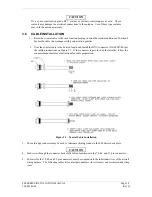
4.5.4 Annunciators/Switches Calibration and Checkout
Refer to section 5.2.8 for the switches checkout. Refer to section 5.2.9 for the annunciators checkout.
4.5.5 Annunciators/Switches
Interconnect
Refer to Figure F-18 on page F-37 for the annunciators/switches interconnect.
Содержание GNC 420
Страница 8: ...Page vi 400 SERIES INSTALLATION MANUAL Rev Q 190 00140 02 This page intentionally left blank ...
Страница 28: ...Page 3 8 400 SERIES INSTALLATION MANUAL Rev Q 190 00140 02 This page intentionally left blank ...
Страница 78: ...Page A 8 400 SERIES INSTALLATION MANUAL Rev Q 190 00140 02 This page intentionally left blank ...
Страница 80: ...Page B 2 400 SERIES INSTALLATION MANUAL Rev Q 190 00140 02 ...
Страница 81: ...400 SERIES INSTALLATION MANUAL Page B 3 190 00140 02 Rev Q ...
Страница 82: ...Page B 4 400 SERIES INSTALLATION MANUAL Rev Q 190 00140 02 ...
Страница 83: ...400 SERIES INSTALLATION MANUAL Page B 5 190 00140 02 Rev Q ...
Страница 84: ...Page B 6 400 SERIES INSTALLATION MANUAL Rev Q 190 00140 02 ...
Страница 85: ...400 SERIES INSTALLATION MANUAL Page B 7 190 00140 02 Rev Q ...
Страница 86: ...Page B 8 400 SERIES INSTALLATION MANUAL Rev Q 190 00140 02 ...
Страница 87: ...400 SERIES INSTALLATION MANUAL Page B 9 190 00140 02 Rev Q ...
Страница 88: ...Page B 10 400 SERIES INSTALLATION MANUAL Rev Q 190 00140 02 This page intentionally left blank ...
Страница 103: ...400 SERIES INSTALLATION MANUAL Page F 3 Page F 4 blank 190 00140 02 Rev Q Figure F 1 GA 56 Antenna Installation Drawing ...
Страница 104: ...400 SERIES INSTALLATION MANUAL Page F 5 Page F 6 blank 190 00140 02 Rev Q Figure F 2 GNS 430 Mounting Rack Dimensions ...
Страница 105: ...400 SERIES INSTALLATION MANUAL Page F 7 Page F 8 blank 190 00140 02 Rev Q Figure F 3 GNC 420 Mounting Rack Dimensions ...
Страница 106: ...400 SERIES INSTALLATION MANUAL Page F 9 Page F 10 blank 190 00140 02 Rev Q Figure F 4 GPS 400 Mounting Rack Dimensions ...
Страница 112: ...400 SERIES INSTALLATION MANUAL Page F 21 Page F 22 blank 190 00140 02 Rev Q Figure F 10 GNS 430 Typical Installation ...
Страница 113: ...400 SERIES INSTALLATION MANUAL Page F 23 Page F 24 blank 190 00140 02 Rev Q Figure F 11 GNC 420 Typical Installation ...
Страница 114: ...400 SERIES INSTALLATION MANUAL Page F 25 Page F 26 blank 190 00140 02 Rev Q Figure F 12 GPS 400 Typical Installation ...
Страница 116: ...400 SERIES INSTALLATION MANUAL Page F 29 Page F 30 blank 190 00140 02 Rev Q Figure F 14 Altimeter Interconnect ...
Страница 117: ...400 SERIES INSTALLATION MANUAL Page F 31 Page F 32 blank 190 00140 02 Rev Q Figure F 15 Main Indicator Interconnect ...
Страница 121: ...400 SERIES INSTALLATION MANUAL Page F 39 Page F 40 blank 190 00140 02 Rev Q Figure F 19 RS 232 Serial Data Interconnect ...
Страница 122: ...400 SERIES INSTALLATION MANUAL Page F 41 Page F 42 blank 190 00140 02 Rev Q Figure F 20 ARINC 429 EFIS Interconnect ...
Страница 130: ...400 SERIES INSTALLATION MANUAL Page F 57 Page F 58 blank 190 00140 02 Rev Q Figure F 28 Audio Panel Interconnect ...
Страница 131: ...400 SERIES INSTALLATION MANUAL Page F 59 Page F 60 blank 190 00140 02 Rev Q Figure F 29 VOR ILS Indicator Interconnect ...
Страница 132: ...400 SERIES INSTALLATION MANUAL Page F 61 Page F 62 blank 190 00140 02 Rev Q Figure F 30 RMI OBI Interconnect ...