


Garmin AT
Rev --
© 2004 Garmin AT
GX Service Manual
7-49
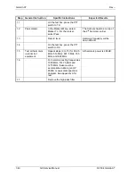
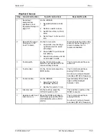
Headset Distortion
Step
General Instruction
Specific Instructions
Expected Results
1 Set
all
test
equipment as
specified in Test
Equipment Setup on
page 7-17.
2
On
the
HP8920:
1. Ext. Load R 100 ohms.
2. AFGen1 to AM 85%.
3. AMPLITUDE to 1,000 µV.
3
Move test cable.
On the test box, connect the
HP8920 audio in cable to HDPH.
4 Adjust
volume
control on Comm
radio for 280 mW.
On the Comm radio, adjust the
volume control until the AC Level
reads 0.280 watts.
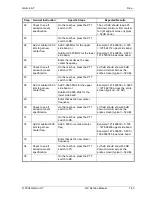
5
On the HP8920, from the one of
many field, select Distn.
Headset at 1000 Hz, distortion
should be < 5%.
6
NOTE: Option 019
required for the
HP8920A.
If Option 019 (the notch filter
option) is not installed, an
external variable notch filter will
be required to complete the
following tests.
7
On the HP8920, push the SHIFT
(blue key) CONFIG keys under
SCREEN CONTROL. Select
Notch Coupl. Set to AFGen1.
Push the PREV key under
SCREEN CONTROL to return to
RX TEST.
Lock notch filter to AF Gen1
Freq.
8
Notch filter freq. to
350.
On the HP8920, set the AFGen1
Freq to 350 Hz.
9
Record distortion.
Will be <12% distortion at 350
Hz.
10
Repeat steps 7 to 9 for every 200
Hz until 2500 Hz.
Audio frequency distortion will
be <12% at AM Depth of
modulation of 85% at 350 Hz to
600 Hz and < 5% from 600 Hz
to 2500 Hz.
Содержание APOLLO GX SERIES
Страница 8: ...Garmin AT Rev viii GX Service Manual 2004 Garmin AT This Page Intentionally Left Blank...
Страница 12: ...Garmin AT Rev 1 4 GX Service Manual 2004 Garmin AT...
Страница 24: ...Garmin AT Rev 2 12 GX Service Manual 2004 Garmin AT...
Страница 26: ...Garmin AT Rev 3 2 GX Service Manual 2004 Garmin AT...
Страница 27: ...2004 Garmin AT GX Service Manual 4 1 Chapter 4 Antenna Installation Guides...
Страница 28: ...Garmin AT Rev 4 2 GX Service Manual 2004 Garmin AT...
Страница 32: ...Garmin AT Rev 5 4 GX Service Manual 2004 Garmin AT...
Страница 96: ...Garmin AT Rev 7 58 GX Service Manual 2004 Garmin AT...
Страница 98: ...Garmin AT Rev 8 2 GX Service Manual 2004 Garmin AT Figure 8 1 GX55 Assembly Board Locations...
Страница 99: ...Garmin AT Rev 2004 Garmin AT GX Service Manual 8 3 Figure 8 2 GX 50 60 65 Assembly Board Locations...
Страница 122: ...Garmin AT Rev 8 26 GX Service Manual 2004 Garmin AT...
Страница 130: ...Garmin AT Rev 9 8 GX Service Manual 2004 Garmin AT...
Страница 136: ...Garmin AT Rev 10 6 GX Service Manual 2004 Garmin AT Figure 10 3 Comm PCB Component Layout Reference Only Sheet 1 of 3...
Страница 137: ...Garmin AT Rev 2004 Garmin AT GX Service Manual 10 7 Figure 10 3 Comm PCB Component Layout Reference Only Sheet 2 of 3...
Страница 138: ...Garmin AT Rev 10 8 GX Service Manual 2004 Garmin AT Figure 10 3 Comm PCB Component Layout Reference Only Sheet 3 of 3...
Страница 139: ...Garmin AT Rev 2004 Garmin AT GX Service Manual 10 9 Block Diagrams Figure 10 4 NAV Block Diagram...
Страница 140: ...Garmin AT Rev 10 10 GX Service Manual 2004 Garmin AT Figure 10 5 Comm Board Block Diagram...
Страница 149: ...Garmin AT Rev 2004 Garmin AT GX Service Manual 10 19 Figure 10 13 GX55 Assembly Reference Only Sheet 2 of 2...
Страница 150: ...Garmin AT Rev 10 20 GX Service Manual 2004 Garmin AT Figure 10 14 GX50 60 65 Assembly Reference Only Sheet 1 of 2...
Страница 152: ...Garmin AT Rev 10 22 GX Service Manual 2004 Garmin AT...
Страница 158: ...Garmin AT Rev 11 6 GX Service Manual 2004 Garmin AT...
Страница 160: ...Garmin AT Rev 12 2 GX Service Manual 2004 Garmin AT...
Страница 161: ...2004 Garmin AT GX Service Manual 13 1 Chapter 13 Service Data Sheet 561 6001 500 GX Series Service Data Sheet...
Страница 162: ...Garmin AT Rev 13 2 GX Service Manual 2004 Garmin AT...
Страница 165: ......
Страница 166: ......


