Garmin AT
Rev --
© 2004 Garmin AT
GX Service Manual
7-15
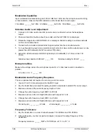
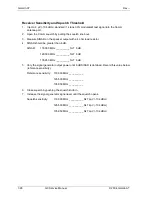
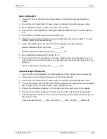
Comm Return to Service Procedure
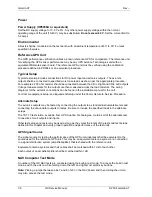
Introduction
Complete the transmitter frequency test before performing the receiver evaluations.
There are no adjustments inside the Comm radio. Several calibration numbers are stored in the
Comm radio EEPROM memory and are factory adjusted for the unit.
Where interference may be a problem, substitute an unused channel as close to the test frequency as
practical. Each test should be performed with the radio channeled on the low, center and high
operating frequencies.
Test Equipment
Test procedures in this manual are described in terms of RF test equipment found in many radio
shops. All test equipment must be current on calibrations. In addition, operating instructions for using
the HP8920 series Communications Test Set, which combines 22 different instruments into one piece
of equipment, are included at the back of the chapter.
Using the HP8920 Communications Test Set
Test set screens are accessed through the front panel CURSOR CONTROL knob. Turning the knob
clockwise or counterclockwise moves the cursor between fields and screens. Pushing the CURSOR
CONTROL knob selects either the field or screen.
Units of measure can be changed to display different measurements in different values or
magnitudes. To change a unit of measurement, position the cursor at the unit field on the display,
press a key labeled with the desired unit of measurement (such as W for watts). If the new units are
valid, the measurement value displays in those units.
To change an underlined entry, use the CURSOR CONTROL knob or the ENTER key to move the
underline to the desired choice.
To make a choice, position the CURSOR CONTROL knob at the field you wish to choose. Push the
CURSOR CONTROL knob or the ENTER key to display the choices. Move the cursor control through
the choices by turning the knob. Push the CURSOR CONTROL knob or the ENTER key to select the
choice.
To change a value, position the cursor at the desired field and key in the value using the DATA
keypad and press Enter or the CURSOR CONTROL knob. The CURSOR CONTROL knob can also
be pushed and rotated to the desired value.
HP8920 Operating Considerations – Measurement Techniques
Applying power to the RF In/Out connector increases the temperature of the internal circuits. This
causes changes in the TX Power measurement especially when measuring low power levels
immediately after high power level measurements. To obtain the best measurement accuracy when
alternately measuring high and low power levels, always zero the power meter immediately before
making low power measurements.
All RF voltages are specified in hard microvolts. Hard microvolts are obtained by inserting a 6 dB (50
ohm) attenuator between the signal generator and the receiver. To obtain hard microvolts when using
the HP8920, use the SHIFT CONFIG keys. Then use the CURSOR CONTROL knob to select RFGen
volts. Push to select EMF. Press PREV in the SCREEN CONTROL menu to return to TX TEST.
Содержание APOLLO GX SERIES
Страница 8: ...Garmin AT Rev viii GX Service Manual 2004 Garmin AT This Page Intentionally Left Blank...
Страница 12: ...Garmin AT Rev 1 4 GX Service Manual 2004 Garmin AT...
Страница 24: ...Garmin AT Rev 2 12 GX Service Manual 2004 Garmin AT...
Страница 26: ...Garmin AT Rev 3 2 GX Service Manual 2004 Garmin AT...
Страница 27: ...2004 Garmin AT GX Service Manual 4 1 Chapter 4 Antenna Installation Guides...
Страница 28: ...Garmin AT Rev 4 2 GX Service Manual 2004 Garmin AT...
Страница 32: ...Garmin AT Rev 5 4 GX Service Manual 2004 Garmin AT...
Страница 96: ...Garmin AT Rev 7 58 GX Service Manual 2004 Garmin AT...
Страница 98: ...Garmin AT Rev 8 2 GX Service Manual 2004 Garmin AT Figure 8 1 GX55 Assembly Board Locations...
Страница 99: ...Garmin AT Rev 2004 Garmin AT GX Service Manual 8 3 Figure 8 2 GX 50 60 65 Assembly Board Locations...
Страница 122: ...Garmin AT Rev 8 26 GX Service Manual 2004 Garmin AT...
Страница 130: ...Garmin AT Rev 9 8 GX Service Manual 2004 Garmin AT...
Страница 136: ...Garmin AT Rev 10 6 GX Service Manual 2004 Garmin AT Figure 10 3 Comm PCB Component Layout Reference Only Sheet 1 of 3...
Страница 137: ...Garmin AT Rev 2004 Garmin AT GX Service Manual 10 7 Figure 10 3 Comm PCB Component Layout Reference Only Sheet 2 of 3...
Страница 138: ...Garmin AT Rev 10 8 GX Service Manual 2004 Garmin AT Figure 10 3 Comm PCB Component Layout Reference Only Sheet 3 of 3...
Страница 139: ...Garmin AT Rev 2004 Garmin AT GX Service Manual 10 9 Block Diagrams Figure 10 4 NAV Block Diagram...
Страница 140: ...Garmin AT Rev 10 10 GX Service Manual 2004 Garmin AT Figure 10 5 Comm Board Block Diagram...
Страница 149: ...Garmin AT Rev 2004 Garmin AT GX Service Manual 10 19 Figure 10 13 GX55 Assembly Reference Only Sheet 2 of 2...
Страница 150: ...Garmin AT Rev 10 20 GX Service Manual 2004 Garmin AT Figure 10 14 GX50 60 65 Assembly Reference Only Sheet 1 of 2...
Страница 152: ...Garmin AT Rev 10 22 GX Service Manual 2004 Garmin AT...
Страница 158: ...Garmin AT Rev 11 6 GX Service Manual 2004 Garmin AT...
Страница 160: ...Garmin AT Rev 12 2 GX Service Manual 2004 Garmin AT...
Страница 161: ...2004 Garmin AT GX Service Manual 13 1 Chapter 13 Service Data Sheet 561 6001 500 GX Series Service Data Sheet...
Страница 162: ...Garmin AT Rev 13 2 GX Service Manual 2004 Garmin AT...
Страница 165: ......
Страница 166: ......

