Garmin AT
Rev --
7-22
GX Service Manual
© 2004 Garmin AT
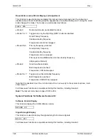
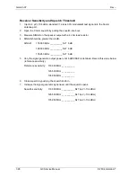
Base Station Lockout Mode Display and Adjustment
This function is used to display and adjust the lockout mode. Improperly set, the lockout can
disable various Comm functions giving the appearance of a malfunctioning unit. Turning the small
knob changes the mode. The modes are summarized as follows.
Locks 000
•
Mode 0:
Normal pilot mode, no disabled functions
•
Mode 1 & 3: Toggle lock, only the Flip/Flop (NRST) button is disabled
Fixed
Primary
frequency
Variable standby frequency
Frequencies cannot be swapped
•
Mode 2 & 6: Primary frequency protected
Fixed primary frequency
Variable standby frequency
Frequencies can be swapped
Primary is not modifiable when it is the standby frequency
(displayed as Mode 6)
•
Mode 4:
Fixed two-channel radio
Both frequencies are fixed
Frequencies CAN be swapped
•
Mode 5 & 7: Toggle lock w/ fixed standby frequency
Both frequencies are fixed
Frequencies CANNOT be swapped
Note that it is possible to put the unit into mode 8, but on re-entry to the system functions, it will
show mode 0.
Full transceiver functions are operational during this function, including transmit.
Note
: The lockout mode has a range of 000 to 008.
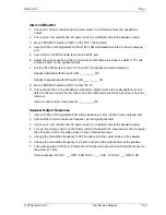
System Functions for Software Version 2.X:
Software Version Display
This function displays the COM software version.
SW VER 2.X
Signal Strength Display
This function is used to display the signal strength of received signals.
RFLVL 087
Full transceiver functions are operational during this function, including transmit.
Содержание APOLLO GX SERIES
Страница 8: ...Garmin AT Rev viii GX Service Manual 2004 Garmin AT This Page Intentionally Left Blank...
Страница 12: ...Garmin AT Rev 1 4 GX Service Manual 2004 Garmin AT...
Страница 24: ...Garmin AT Rev 2 12 GX Service Manual 2004 Garmin AT...
Страница 26: ...Garmin AT Rev 3 2 GX Service Manual 2004 Garmin AT...
Страница 27: ...2004 Garmin AT GX Service Manual 4 1 Chapter 4 Antenna Installation Guides...
Страница 28: ...Garmin AT Rev 4 2 GX Service Manual 2004 Garmin AT...
Страница 32: ...Garmin AT Rev 5 4 GX Service Manual 2004 Garmin AT...
Страница 96: ...Garmin AT Rev 7 58 GX Service Manual 2004 Garmin AT...
Страница 98: ...Garmin AT Rev 8 2 GX Service Manual 2004 Garmin AT Figure 8 1 GX55 Assembly Board Locations...
Страница 99: ...Garmin AT Rev 2004 Garmin AT GX Service Manual 8 3 Figure 8 2 GX 50 60 65 Assembly Board Locations...
Страница 122: ...Garmin AT Rev 8 26 GX Service Manual 2004 Garmin AT...
Страница 130: ...Garmin AT Rev 9 8 GX Service Manual 2004 Garmin AT...
Страница 136: ...Garmin AT Rev 10 6 GX Service Manual 2004 Garmin AT Figure 10 3 Comm PCB Component Layout Reference Only Sheet 1 of 3...
Страница 137: ...Garmin AT Rev 2004 Garmin AT GX Service Manual 10 7 Figure 10 3 Comm PCB Component Layout Reference Only Sheet 2 of 3...
Страница 138: ...Garmin AT Rev 10 8 GX Service Manual 2004 Garmin AT Figure 10 3 Comm PCB Component Layout Reference Only Sheet 3 of 3...
Страница 139: ...Garmin AT Rev 2004 Garmin AT GX Service Manual 10 9 Block Diagrams Figure 10 4 NAV Block Diagram...
Страница 140: ...Garmin AT Rev 10 10 GX Service Manual 2004 Garmin AT Figure 10 5 Comm Board Block Diagram...
Страница 149: ...Garmin AT Rev 2004 Garmin AT GX Service Manual 10 19 Figure 10 13 GX55 Assembly Reference Only Sheet 2 of 2...
Страница 150: ...Garmin AT Rev 10 20 GX Service Manual 2004 Garmin AT Figure 10 14 GX50 60 65 Assembly Reference Only Sheet 1 of 2...
Страница 152: ...Garmin AT Rev 10 22 GX Service Manual 2004 Garmin AT...
Страница 158: ...Garmin AT Rev 11 6 GX Service Manual 2004 Garmin AT...
Страница 160: ...Garmin AT Rev 12 2 GX Service Manual 2004 Garmin AT...
Страница 161: ...2004 Garmin AT GX Service Manual 13 1 Chapter 13 Service Data Sheet 561 6001 500 GX Series Service Data Sheet...
Страница 162: ...Garmin AT Rev 13 2 GX Service Manual 2004 Garmin AT...
Страница 165: ......
Страница 166: ......

