Garmin AT
Rev --
7-46
GX Service Manual
© 2004 Garmin AT
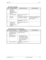
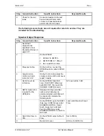
Intercom/Monitor
Step
General Instruction
Specific Instructions
Expected Results
1 Set
all
test
equipment as
specified in Test
Equipment Setup on
page 7-17.
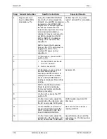
On the HP8920:
1. Set AMPLITUDE to 1000
µV.
2. Set Ext. Load R 4 ohms.
3. Set AFGen1 Freq. to 500
Hz. Set AFGen2 Freq. to
2000 Hz.
4. Set AFGen2 To field to
Audio out at 50 mV.
2 Adjust
volume
control on Comm
radio for 12 W.
On the Comm radio, adjust the
volume control until the AC Level
reads 12 watts.
≥
12 watts output into 4 ohm
load (mounted in test fixture) at
a volume level from 0 to 12
watts.
3
Mute speaker test.
On the test box, set INT/OFF
switch to INT.
The speaker audio out will be
0 W.
When the Intercom switch is on,
the speaker is disabled.
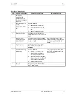
4
Check headset.
On the test box:
1. Move the SPKR OUT cable
to the HDPH test jack.
2. Set the TEST HDPH/LOAD
switch to TEST HDPH.
When the Intercom switch is on,
the Comm radio signal is routed
to the headphones.
5 Check
headset
volume.
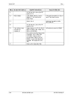
On the HP8920 set:
1. EXT LOAD TO R to 100
ohms.
2. Adjust the volume control on
the HP8920 to monitor the
0.500 kHz tone.
The HP8920 AF Freq. meter
will read 0.500 kHz ± 15 Hz.
6
On the Comm radio, adjust
volume control to read 0.280
watts on the HP8920 AC Level
meter.
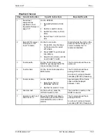
7
Set to reference.
On the HP8920, select the AC
Level Field (W), then press
SHIFT REF SET and push
CURSOR CONTROL knob.
The Comm channel is set as
reference audio level.
8 Check
if
microphone
mutes radio.
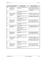
On the test box move the
TEST/MIC1 switch to MIC1.
The HP8920:
1. AF Freq. meter will read
1500 Hz ± 15 Hz.
2. The AC Level Meter will
read 1 dB greater than
reference.
Содержание APOLLO GX SERIES
Страница 8: ...Garmin AT Rev viii GX Service Manual 2004 Garmin AT This Page Intentionally Left Blank...
Страница 12: ...Garmin AT Rev 1 4 GX Service Manual 2004 Garmin AT...
Страница 24: ...Garmin AT Rev 2 12 GX Service Manual 2004 Garmin AT...
Страница 26: ...Garmin AT Rev 3 2 GX Service Manual 2004 Garmin AT...
Страница 27: ...2004 Garmin AT GX Service Manual 4 1 Chapter 4 Antenna Installation Guides...
Страница 28: ...Garmin AT Rev 4 2 GX Service Manual 2004 Garmin AT...
Страница 32: ...Garmin AT Rev 5 4 GX Service Manual 2004 Garmin AT...
Страница 96: ...Garmin AT Rev 7 58 GX Service Manual 2004 Garmin AT...
Страница 98: ...Garmin AT Rev 8 2 GX Service Manual 2004 Garmin AT Figure 8 1 GX55 Assembly Board Locations...
Страница 99: ...Garmin AT Rev 2004 Garmin AT GX Service Manual 8 3 Figure 8 2 GX 50 60 65 Assembly Board Locations...
Страница 122: ...Garmin AT Rev 8 26 GX Service Manual 2004 Garmin AT...
Страница 130: ...Garmin AT Rev 9 8 GX Service Manual 2004 Garmin AT...
Страница 136: ...Garmin AT Rev 10 6 GX Service Manual 2004 Garmin AT Figure 10 3 Comm PCB Component Layout Reference Only Sheet 1 of 3...
Страница 137: ...Garmin AT Rev 2004 Garmin AT GX Service Manual 10 7 Figure 10 3 Comm PCB Component Layout Reference Only Sheet 2 of 3...
Страница 138: ...Garmin AT Rev 10 8 GX Service Manual 2004 Garmin AT Figure 10 3 Comm PCB Component Layout Reference Only Sheet 3 of 3...
Страница 139: ...Garmin AT Rev 2004 Garmin AT GX Service Manual 10 9 Block Diagrams Figure 10 4 NAV Block Diagram...
Страница 140: ...Garmin AT Rev 10 10 GX Service Manual 2004 Garmin AT Figure 10 5 Comm Board Block Diagram...
Страница 149: ...Garmin AT Rev 2004 Garmin AT GX Service Manual 10 19 Figure 10 13 GX55 Assembly Reference Only Sheet 2 of 2...
Страница 150: ...Garmin AT Rev 10 20 GX Service Manual 2004 Garmin AT Figure 10 14 GX50 60 65 Assembly Reference Only Sheet 1 of 2...
Страница 152: ...Garmin AT Rev 10 22 GX Service Manual 2004 Garmin AT...
Страница 158: ...Garmin AT Rev 11 6 GX Service Manual 2004 Garmin AT...
Страница 160: ...Garmin AT Rev 12 2 GX Service Manual 2004 Garmin AT...
Страница 161: ...2004 Garmin AT GX Service Manual 13 1 Chapter 13 Service Data Sheet 561 6001 500 GX Series Service Data Sheet...
Страница 162: ...Garmin AT Rev 13 2 GX Service Manual 2004 Garmin AT...
Страница 165: ......
Страница 166: ......


