Garmin AT
Rev --
7-52
GX Service Manual
© 2004 Garmin AT
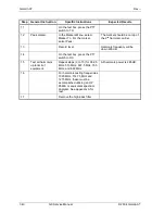
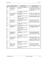
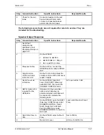
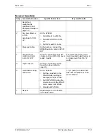
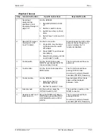
Receiver Dynamic Range
Step
General Instruction
Specific Instructions
Expected Results
1 Set
all
test
equipment as
specified in Test
Equipment Setup on
page 7-17.
2
RF Out to Dupl. Sig.
Gen. Mod Lvl. To
30%.
Amplitude to 1000
µV.
On the HP8920:
1. Set RF OUT/Dupl.
2. Set AFGen1 to AM 30%.
3. Set AMPLITUDE to 1000
µV.
4. Set Ext. Load R 4 ohms.
3
Move RF cable.
On the HP8920, move the
RFIN/OUT cable to DUPLEX out
connector.
4 Adjust
volume
control on Comm
radio for 12 W.
On the Comm radio, adjust the
volume control until the AC Level
reads 12 watts.
≥
12 watts output into 4 ohm
load (mounted in test fixture) at
a volume level from 0 to 12
watts.
5
Open squelch.
On the Comm radio, pull the
Squelch knob out (disable
squelch).
6
Find 6 dB SINAD
reading.
On the HP8920, set the value
field in the SINAD meter reading
to average (AVG) at 10.
Set AMPLITUDE using the
↑
↓
arrows until the SINAD meter
reads 6 dB SINAD.
Reference signal level
≤
2 µV
(hard) for 6 dB S+N/N with 30%
modulation at 1000 Hz.
7
Add 107dB.
On the HP8920:
1. Select the AMPLITUDE field.
Press the GHz/dBm key.
2. To calculate upper dynamic
range, add 107dB to
reference signal level.
Converts µV to dBm.
Example: –107 dBm +107 = 0
dBm.
8
Set HP8920 to 224
mV.
On the HP8920:
1. Set the AMPLITUDE field to
upper dynamic range.
2. Select the SINAD field and
change to Distn.
Dynamic range is 107 dB with
<5% distortion.
9
Record as pass or fail.
Содержание APOLLO GX SERIES
Страница 8: ...Garmin AT Rev viii GX Service Manual 2004 Garmin AT This Page Intentionally Left Blank...
Страница 12: ...Garmin AT Rev 1 4 GX Service Manual 2004 Garmin AT...
Страница 24: ...Garmin AT Rev 2 12 GX Service Manual 2004 Garmin AT...
Страница 26: ...Garmin AT Rev 3 2 GX Service Manual 2004 Garmin AT...
Страница 27: ...2004 Garmin AT GX Service Manual 4 1 Chapter 4 Antenna Installation Guides...
Страница 28: ...Garmin AT Rev 4 2 GX Service Manual 2004 Garmin AT...
Страница 32: ...Garmin AT Rev 5 4 GX Service Manual 2004 Garmin AT...
Страница 96: ...Garmin AT Rev 7 58 GX Service Manual 2004 Garmin AT...
Страница 98: ...Garmin AT Rev 8 2 GX Service Manual 2004 Garmin AT Figure 8 1 GX55 Assembly Board Locations...
Страница 99: ...Garmin AT Rev 2004 Garmin AT GX Service Manual 8 3 Figure 8 2 GX 50 60 65 Assembly Board Locations...
Страница 122: ...Garmin AT Rev 8 26 GX Service Manual 2004 Garmin AT...
Страница 130: ...Garmin AT Rev 9 8 GX Service Manual 2004 Garmin AT...
Страница 136: ...Garmin AT Rev 10 6 GX Service Manual 2004 Garmin AT Figure 10 3 Comm PCB Component Layout Reference Only Sheet 1 of 3...
Страница 137: ...Garmin AT Rev 2004 Garmin AT GX Service Manual 10 7 Figure 10 3 Comm PCB Component Layout Reference Only Sheet 2 of 3...
Страница 138: ...Garmin AT Rev 10 8 GX Service Manual 2004 Garmin AT Figure 10 3 Comm PCB Component Layout Reference Only Sheet 3 of 3...
Страница 139: ...Garmin AT Rev 2004 Garmin AT GX Service Manual 10 9 Block Diagrams Figure 10 4 NAV Block Diagram...
Страница 140: ...Garmin AT Rev 10 10 GX Service Manual 2004 Garmin AT Figure 10 5 Comm Board Block Diagram...
Страница 149: ...Garmin AT Rev 2004 Garmin AT GX Service Manual 10 19 Figure 10 13 GX55 Assembly Reference Only Sheet 2 of 2...
Страница 150: ...Garmin AT Rev 10 20 GX Service Manual 2004 Garmin AT Figure 10 14 GX50 60 65 Assembly Reference Only Sheet 1 of 2...
Страница 152: ...Garmin AT Rev 10 22 GX Service Manual 2004 Garmin AT...
Страница 158: ...Garmin AT Rev 11 6 GX Service Manual 2004 Garmin AT...
Страница 160: ...Garmin AT Rev 12 2 GX Service Manual 2004 Garmin AT...
Страница 161: ...2004 Garmin AT GX Service Manual 13 1 Chapter 13 Service Data Sheet 561 6001 500 GX Series Service Data Sheet...
Страница 162: ...Garmin AT Rev 13 2 GX Service Manual 2004 Garmin AT...
Страница 165: ......
Страница 166: ......


