


Garmin AT
Rev --
8-20
GX Service Manual
© 2004 Garmin AT
NAV Board Replacement
This procedure describes the removal and replacement of the NAV board.
Parts Required
•
221-0401 SCREW, PAN HEAD PHILIPS, 4-40 X ¼" W/SPLIT LOCK WASHER, STAINLESS
STEEL (8 required for GX55, 4 required for GX50/60/65)
•
224-0403 SCREW, UNDERCUT, PAN HEAD PHILIPS, 4-40 X 3/16", 82 DEGREE, STAINLESS
STEEL (4 required for GX55, 3 required for GX50/60/65)
•
415-7004-00 NAVIGATION COMPUTER BOARD, GX50/60/65
•
415-7004-20 NAVIGATION COMPUTER BOARD, GX55
Removal
1. Before starting this procedure, fill out a Service Data Sheet if this has not already been done. A
copy is located at the back of this manual.
2. Power the unit off and disconnect power from the unit.
3. Remove the bezel assembly (see Bezel Assembly Replacement procedure).
4. On the GX60/ 65, remove the Comm board first (see Comm Board Replacement procedure).
5. Remove the GPS board (see GX50/55 or GX60/65 GPS Board Replacement procedure).
6. Remove the screws (four on the GX55, three on the GX50/60/65) holding down the NAV board.
7. Remove the outer screw from the right side of the chassis.
8. Remove the screws (four on the GX55, two on the GX50/60/65) that hold the D-sub connector on
the back of the chassis.
9. On the GX55, remove the filler plate by sliding it up out of the rear of the chassis.
10. Lift the NAV board from the chassis.
Replacement
1. Put the new NAV board (see the Parts Required section above for the correct part number) in
place in the chassis on the right side.
2. On the GX55, replace the filler plate on the back of the chassis.
3. Replace the screws (221-0401) (four on the GX55, two on the GX50/60/65) that hold the D-sub
connector on the back of the chassis.
Torque the screws to 5.0 lb.-in.
4. Replace the screw (224-0403) on the outside that holds the NAV board.
Torque the screw to 5.0
lb.-in.
5. Replace the screws (221-0401) (four GX55, three on the GX50/60/65) that hold down the NAV
board.
Torque the screws to 5.0 lb.-in.
6. Replace the GPS board (see GX50/55 or GX60/65 GPS Board Replacement procedure).
7. On the GX60/ 65, replace the Comm board (see Comm Board Replacement procedure).
8. Replace the bezel assembly (see Bezel Assembly Replacement procedure).
9. Completely reinitialize the unit (see Complete Initialization procedure).
10. Test the unit to verify proper operation (see Return to Service procedures).
11. Using the Service Data Sheet, reenter the customer configuration.
Содержание APOLLO GX SERIES
Страница 8: ...Garmin AT Rev viii GX Service Manual 2004 Garmin AT This Page Intentionally Left Blank...
Страница 12: ...Garmin AT Rev 1 4 GX Service Manual 2004 Garmin AT...
Страница 24: ...Garmin AT Rev 2 12 GX Service Manual 2004 Garmin AT...
Страница 26: ...Garmin AT Rev 3 2 GX Service Manual 2004 Garmin AT...
Страница 27: ...2004 Garmin AT GX Service Manual 4 1 Chapter 4 Antenna Installation Guides...
Страница 28: ...Garmin AT Rev 4 2 GX Service Manual 2004 Garmin AT...
Страница 32: ...Garmin AT Rev 5 4 GX Service Manual 2004 Garmin AT...
Страница 96: ...Garmin AT Rev 7 58 GX Service Manual 2004 Garmin AT...
Страница 98: ...Garmin AT Rev 8 2 GX Service Manual 2004 Garmin AT Figure 8 1 GX55 Assembly Board Locations...
Страница 99: ...Garmin AT Rev 2004 Garmin AT GX Service Manual 8 3 Figure 8 2 GX 50 60 65 Assembly Board Locations...
Страница 122: ...Garmin AT Rev 8 26 GX Service Manual 2004 Garmin AT...
Страница 130: ...Garmin AT Rev 9 8 GX Service Manual 2004 Garmin AT...
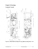
Страница 136: ...Garmin AT Rev 10 6 GX Service Manual 2004 Garmin AT Figure 10 3 Comm PCB Component Layout Reference Only Sheet 1 of 3...
Страница 137: ...Garmin AT Rev 2004 Garmin AT GX Service Manual 10 7 Figure 10 3 Comm PCB Component Layout Reference Only Sheet 2 of 3...
Страница 138: ...Garmin AT Rev 10 8 GX Service Manual 2004 Garmin AT Figure 10 3 Comm PCB Component Layout Reference Only Sheet 3 of 3...
Страница 139: ...Garmin AT Rev 2004 Garmin AT GX Service Manual 10 9 Block Diagrams Figure 10 4 NAV Block Diagram...
Страница 140: ...Garmin AT Rev 10 10 GX Service Manual 2004 Garmin AT Figure 10 5 Comm Board Block Diagram...
Страница 149: ...Garmin AT Rev 2004 Garmin AT GX Service Manual 10 19 Figure 10 13 GX55 Assembly Reference Only Sheet 2 of 2...
Страница 150: ...Garmin AT Rev 10 20 GX Service Manual 2004 Garmin AT Figure 10 14 GX50 60 65 Assembly Reference Only Sheet 1 of 2...
Страница 152: ...Garmin AT Rev 10 22 GX Service Manual 2004 Garmin AT...
Страница 158: ...Garmin AT Rev 11 6 GX Service Manual 2004 Garmin AT...
Страница 160: ...Garmin AT Rev 12 2 GX Service Manual 2004 Garmin AT...
Страница 161: ...2004 Garmin AT GX Service Manual 13 1 Chapter 13 Service Data Sheet 561 6001 500 GX Series Service Data Sheet...
Страница 162: ...Garmin AT Rev 13 2 GX Service Manual 2004 Garmin AT...
Страница 165: ......
Страница 166: ......