


Garmin AT
Rev --
© 2004 Garmin AT
GX Service Manual
8-17
Knob Replacement
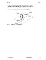
This procedure describes the removal and replacement of the rotary knobs on the front of the bezel
assembly.
Parts Required
•
230-0402 SCREW, SET, 4-40 X 1/8" (3 required)
•
262-0049 KNOB, POWER DZUS RAIL NMC
•
262-0052-00 KNOB, INNER CONCENTRIC
•
262-0053-00 KNOB, OUTER CONCENTRIC
•
664-0042
LOCTITE,
242
Removal
1. Before starting this procedure, fill out a Service Data Sheet if this has not already been done. A
copy is located at the back of this manual.
2. Power the unit off and disconnect power from the unit.
3. Remove the three knobs from the front of the bezel assembly using the 0.050" hex driver.
Replacement
1. Replace the three knobs (262-0049, -0052,-0053) as needed. Apply Loctite (664-0042) to the
setscrews (230-0402). Tighten the setscrews using the 0.050" hex driver. Space the knobs 0.010"
off the bezel assembly so they will turn smoothly. Space the outer knob from the large knob
slightly so that it will turn freely while keeping the bottom of the small knob inside the cavity of the
large knob.
2. Test the unit to verify proper operation (see Return to Service procedures).
3. Using the Service Data Sheet, reenter the customer configuration.
Содержание APOLLO GX SERIES
Страница 8: ...Garmin AT Rev viii GX Service Manual 2004 Garmin AT This Page Intentionally Left Blank...
Страница 12: ...Garmin AT Rev 1 4 GX Service Manual 2004 Garmin AT...
Страница 24: ...Garmin AT Rev 2 12 GX Service Manual 2004 Garmin AT...
Страница 26: ...Garmin AT Rev 3 2 GX Service Manual 2004 Garmin AT...
Страница 27: ...2004 Garmin AT GX Service Manual 4 1 Chapter 4 Antenna Installation Guides...
Страница 28: ...Garmin AT Rev 4 2 GX Service Manual 2004 Garmin AT...
Страница 32: ...Garmin AT Rev 5 4 GX Service Manual 2004 Garmin AT...
Страница 96: ...Garmin AT Rev 7 58 GX Service Manual 2004 Garmin AT...
Страница 98: ...Garmin AT Rev 8 2 GX Service Manual 2004 Garmin AT Figure 8 1 GX55 Assembly Board Locations...
Страница 99: ...Garmin AT Rev 2004 Garmin AT GX Service Manual 8 3 Figure 8 2 GX 50 60 65 Assembly Board Locations...
Страница 122: ...Garmin AT Rev 8 26 GX Service Manual 2004 Garmin AT...
Страница 130: ...Garmin AT Rev 9 8 GX Service Manual 2004 Garmin AT...
Страница 136: ...Garmin AT Rev 10 6 GX Service Manual 2004 Garmin AT Figure 10 3 Comm PCB Component Layout Reference Only Sheet 1 of 3...
Страница 137: ...Garmin AT Rev 2004 Garmin AT GX Service Manual 10 7 Figure 10 3 Comm PCB Component Layout Reference Only Sheet 2 of 3...
Страница 138: ...Garmin AT Rev 10 8 GX Service Manual 2004 Garmin AT Figure 10 3 Comm PCB Component Layout Reference Only Sheet 3 of 3...
Страница 139: ...Garmin AT Rev 2004 Garmin AT GX Service Manual 10 9 Block Diagrams Figure 10 4 NAV Block Diagram...
Страница 140: ...Garmin AT Rev 10 10 GX Service Manual 2004 Garmin AT Figure 10 5 Comm Board Block Diagram...
Страница 149: ...Garmin AT Rev 2004 Garmin AT GX Service Manual 10 19 Figure 10 13 GX55 Assembly Reference Only Sheet 2 of 2...
Страница 150: ...Garmin AT Rev 10 20 GX Service Manual 2004 Garmin AT Figure 10 14 GX50 60 65 Assembly Reference Only Sheet 1 of 2...
Страница 152: ...Garmin AT Rev 10 22 GX Service Manual 2004 Garmin AT...
Страница 158: ...Garmin AT Rev 11 6 GX Service Manual 2004 Garmin AT...
Страница 160: ...Garmin AT Rev 12 2 GX Service Manual 2004 Garmin AT...
Страница 161: ...2004 Garmin AT GX Service Manual 13 1 Chapter 13 Service Data Sheet 561 6001 500 GX Series Service Data Sheet...
Страница 162: ...Garmin AT Rev 13 2 GX Service Manual 2004 Garmin AT...
Страница 165: ......
Страница 166: ......