


Garmin AT
Rev --
© 2004 Garmin AT
GX Service Manual
7-21
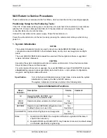
Note:
The noise level is an 8-bit value with a range of 0 to 255 from the noise level detector as
read into the µcontroller through an A/D input.
While viewing the frequency display, use the large and small knobs to select an unused local
frequency. Toggle this frequency to the active channel. Press and hold the MON
button for about
3 seconds to reach the System Functions. Use the large knob to select the NOISE function and
view the receive noise level of the selected frequency. The value will change constantly, and has
a range between 0 and 255. On the service bench with the antenna port of the transceiver
connected to a dummy load, NOISE should be between 100 and 125. If the transceiver is
connected to the aircraft antenna and there is no carrier on the channel, expect the reading to be
the same or slightly higher. To confirm that there is no carrier on the monitored channel, pull the
squelch knob and listen.
Headphone Level Display and Adjustment
This function is used to display and adjust the headphone audio level. Turning the small knob
changes the value. Setting the value to 0 slaves the headphone audio level to the volume control
knob. Setting to a non-zero value gives a fixed headphone audio level.
HphLv 015
Full transceiver functions are operational during this function, including transmit.
Note:
The headphone level is an 8-bit value with a range of 0 to 255.
Intercom Squelch Threshold Display and Adjustment
This function is used to display and adjust the intercom squelch threshold level. Turning the small
knob changes the threshold.
IcmSq 200
Full transceiver functions are operational during this function, including transmit.
Note:
The intercom squelch threshold level is an 8-bit value with a range of 0 to 255.
Intercom Audio Level Display and Adjustment
This function is used to display and adjust the intercom audio level. Turning the small knob
changes the value. Setting the value to 0 slaves the intercom level to the volume control knob.
Setting to a non-zero value gives a fixed intercom audio level.
IcmLv 000
Full transceiver functions are operational during this function, including transmit.
Note:
The intercom level is an 8-bit value with a range of 0 to 255.
Sidetone Level Display and Adjustment
This function is used to display and adjust the sidetone audio level. Turning the small knob
changes the value. Setting the value to 0 slaves the sidetone audio level to the volume control
knob. Setting to a non-zero value gives a fixed sidetone audio level.
SidLv 000
Full transceiver functions are operational during this function, including transmit.
Note:
The sidetone level is an 8-bit value with a range of 0 to 255.
Содержание APOLLO GX SERIES
Страница 8: ...Garmin AT Rev viii GX Service Manual 2004 Garmin AT This Page Intentionally Left Blank...
Страница 12: ...Garmin AT Rev 1 4 GX Service Manual 2004 Garmin AT...
Страница 24: ...Garmin AT Rev 2 12 GX Service Manual 2004 Garmin AT...
Страница 26: ...Garmin AT Rev 3 2 GX Service Manual 2004 Garmin AT...
Страница 27: ...2004 Garmin AT GX Service Manual 4 1 Chapter 4 Antenna Installation Guides...
Страница 28: ...Garmin AT Rev 4 2 GX Service Manual 2004 Garmin AT...
Страница 32: ...Garmin AT Rev 5 4 GX Service Manual 2004 Garmin AT...
Страница 96: ...Garmin AT Rev 7 58 GX Service Manual 2004 Garmin AT...
Страница 98: ...Garmin AT Rev 8 2 GX Service Manual 2004 Garmin AT Figure 8 1 GX55 Assembly Board Locations...
Страница 99: ...Garmin AT Rev 2004 Garmin AT GX Service Manual 8 3 Figure 8 2 GX 50 60 65 Assembly Board Locations...
Страница 122: ...Garmin AT Rev 8 26 GX Service Manual 2004 Garmin AT...
Страница 130: ...Garmin AT Rev 9 8 GX Service Manual 2004 Garmin AT...
Страница 136: ...Garmin AT Rev 10 6 GX Service Manual 2004 Garmin AT Figure 10 3 Comm PCB Component Layout Reference Only Sheet 1 of 3...
Страница 137: ...Garmin AT Rev 2004 Garmin AT GX Service Manual 10 7 Figure 10 3 Comm PCB Component Layout Reference Only Sheet 2 of 3...
Страница 138: ...Garmin AT Rev 10 8 GX Service Manual 2004 Garmin AT Figure 10 3 Comm PCB Component Layout Reference Only Sheet 3 of 3...
Страница 139: ...Garmin AT Rev 2004 Garmin AT GX Service Manual 10 9 Block Diagrams Figure 10 4 NAV Block Diagram...
Страница 140: ...Garmin AT Rev 10 10 GX Service Manual 2004 Garmin AT Figure 10 5 Comm Board Block Diagram...
Страница 149: ...Garmin AT Rev 2004 Garmin AT GX Service Manual 10 19 Figure 10 13 GX55 Assembly Reference Only Sheet 2 of 2...
Страница 150: ...Garmin AT Rev 10 20 GX Service Manual 2004 Garmin AT Figure 10 14 GX50 60 65 Assembly Reference Only Sheet 1 of 2...
Страница 152: ...Garmin AT Rev 10 22 GX Service Manual 2004 Garmin AT...
Страница 158: ...Garmin AT Rev 11 6 GX Service Manual 2004 Garmin AT...
Страница 160: ...Garmin AT Rev 12 2 GX Service Manual 2004 Garmin AT...
Страница 161: ...2004 Garmin AT GX Service Manual 13 1 Chapter 13 Service Data Sheet 561 6001 500 GX Series Service Data Sheet...
Страница 162: ...Garmin AT Rev 13 2 GX Service Manual 2004 Garmin AT...
Страница 165: ......
Страница 166: ......