


Garmin AT
Rev --
8-10
GX Service Manual
© 2004 Garmin AT
GX60/65 Comm Board Replacement
This procedure describes the removal and replacement of the Comm board.
Parts Required
•
221-0401 PAN HEAD PHILIPS, 4-40 x ¼” w/ SPLIT LOCK WASHER, STAINLESS STEEL (10
required)
•
224-0404 UNDERCUT, PAN HEAD PHILIPS, 4-40 x ¼”, 82 DEGREE, STAINLESS STEEL (2
required)
•
415-7002-00 PRINTED CIRCUIT ASSEMBLY, VHF Comm, MAIN BOARD, 6011
•
664-0009 HEAT SINK COMPOUND
Removal
1. Before starting this procedure, fill out a Service Data Sheet if this has not already been done. A
copy is located at the back of this manual.
2. Power the unit off and disconnect power from the unit.
3. Remove the chassis cover (see Chassis Cover Replacement procedure).
4. Remove the bezel assembly (see Bezel Assembly Replacement procedure).
5. Remove the nut and lock washer on the BNC connector at the outside back of the chassis.
6. Unplug the ribbon connector from J606 on the Comm board.
7. Remove the two screws on rear of chassis holding the D-sub connector.
8. Remove the two screws from the transistor Q303 on the Comm board. One is accessed through
hole in shielding.
9. Remove the other eight screws holding the Comm board to the chassis.
10. Remove the Comm board from the chassis.
Replacement
1. Put a light coat of heat sink compound on transistor Q303 heat sink.
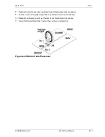
2. Place the Comm board (415-7002-00) in the chassis with the BNC connector exiting the hole at
the back of the chassis.
3. Replace the two screws (221-0401) for Q303 on the Comm board. One screw is accessed
through hole in shielding. Use needle-nosed pliers if needed to place the screw.
Torque screws
to 5.0 lb.-in
.
4. Replace the other eight (221-0401) screws holding the Comm board to the chassis.
Torque
screws to 5.0 lb.-in
.
5. Replace the two screws (224-0404) at the back of chassis holding the D-sub connector P400.
Torque screws to 5.0 lb.-in
.
6. Plug in the ribbon cable that goes from J4 on the NAV board into J606. The red side of the ribbon
cable goes towards the front of the radio. The ribbon cable exits each connector towards the
outside of the radio and loops over the connectors to the other board. See Figure 8-4.
Note:
Avoid misplacement of the connectors on the headers.
7. Replace the nut and lock washer on the BNC connector at the back of the chassis.
Содержание APOLLO GX SERIES
Страница 8: ...Garmin AT Rev viii GX Service Manual 2004 Garmin AT This Page Intentionally Left Blank...
Страница 12: ...Garmin AT Rev 1 4 GX Service Manual 2004 Garmin AT...
Страница 24: ...Garmin AT Rev 2 12 GX Service Manual 2004 Garmin AT...
Страница 26: ...Garmin AT Rev 3 2 GX Service Manual 2004 Garmin AT...
Страница 27: ...2004 Garmin AT GX Service Manual 4 1 Chapter 4 Antenna Installation Guides...
Страница 28: ...Garmin AT Rev 4 2 GX Service Manual 2004 Garmin AT...
Страница 32: ...Garmin AT Rev 5 4 GX Service Manual 2004 Garmin AT...
Страница 96: ...Garmin AT Rev 7 58 GX Service Manual 2004 Garmin AT...
Страница 98: ...Garmin AT Rev 8 2 GX Service Manual 2004 Garmin AT Figure 8 1 GX55 Assembly Board Locations...
Страница 99: ...Garmin AT Rev 2004 Garmin AT GX Service Manual 8 3 Figure 8 2 GX 50 60 65 Assembly Board Locations...
Страница 122: ...Garmin AT Rev 8 26 GX Service Manual 2004 Garmin AT...
Страница 130: ...Garmin AT Rev 9 8 GX Service Manual 2004 Garmin AT...
Страница 136: ...Garmin AT Rev 10 6 GX Service Manual 2004 Garmin AT Figure 10 3 Comm PCB Component Layout Reference Only Sheet 1 of 3...
Страница 137: ...Garmin AT Rev 2004 Garmin AT GX Service Manual 10 7 Figure 10 3 Comm PCB Component Layout Reference Only Sheet 2 of 3...
Страница 138: ...Garmin AT Rev 10 8 GX Service Manual 2004 Garmin AT Figure 10 3 Comm PCB Component Layout Reference Only Sheet 3 of 3...
Страница 139: ...Garmin AT Rev 2004 Garmin AT GX Service Manual 10 9 Block Diagrams Figure 10 4 NAV Block Diagram...
Страница 140: ...Garmin AT Rev 10 10 GX Service Manual 2004 Garmin AT Figure 10 5 Comm Board Block Diagram...
Страница 149: ...Garmin AT Rev 2004 Garmin AT GX Service Manual 10 19 Figure 10 13 GX55 Assembly Reference Only Sheet 2 of 2...
Страница 150: ...Garmin AT Rev 10 20 GX Service Manual 2004 Garmin AT Figure 10 14 GX50 60 65 Assembly Reference Only Sheet 1 of 2...
Страница 152: ...Garmin AT Rev 10 22 GX Service Manual 2004 Garmin AT...
Страница 158: ...Garmin AT Rev 11 6 GX Service Manual 2004 Garmin AT...
Страница 160: ...Garmin AT Rev 12 2 GX Service Manual 2004 Garmin AT...
Страница 161: ...2004 Garmin AT GX Service Manual 13 1 Chapter 13 Service Data Sheet 561 6001 500 GX Series Service Data Sheet...
Страница 162: ...Garmin AT Rev 13 2 GX Service Manual 2004 Garmin AT...
Страница 165: ......
Страница 166: ......


