


Garmin AT
Rev --
© 2004 Garmin AT
GX Service Manual
6-5
Comm Theory of Operation
Design Overview
Module Functionality
The transceiver functions are fully self-contained on the Comm main board printed circuit assembly
(PCA). The Comm PCA is an AM VHF communications transceiver designed for aviation use. The
Comm PCA includes both receive and transmit functions, microphone inputs, and headphone and
speaker outputs.
Circuit Overview
The Comm transceiver is controlled by an Atmel 82C52 8-bit µcontroller. Full power supply circuits
are included. The µcontroller takes inputs from a control panel to determine receive and transmit
frequency, and outputs data to a display for the user.
The µcontroller programs the synthesizer for the selected frequency, adding 21.4 MHz for receive.
The µcontroller monitors status inputs such as synthesizer lock to ensure proper operation and
transmission on valid frequencies.
Complete block diagrams for the Comm module are included in the Drawings Chapter of this manual.
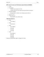
Transmitter
Emission Type
A3E
Frequency Range
The frequency range of the transmitter is 118.000 to 136.975 MHz using 760 channels at 25 kHz
spacing. The user or pilot makes frequency selection.
Output Power
With an input voltage of 12 to 40 volts DC, the transmit output power level is a minimum of 8 watts
and a maximum of 11 watts across the operating frequency range. The output power drops off below
12 volts input to protect the circuit devices and reduce current input during low voltage operation
(aircraft power system failing). The modulation level is held within 5% as the voltage drops, ensuring
the modulation level remains below 95%.
Modulation Level
The modulation level is controlled by the analog circuits and a D/A converter used as a gain control
and is limited by an AGC circuit and calibration.
The microphone inputs are amplified in a preamp, then switched through to an automatic gain control
(AGC) circuit. The AGC circuit provides limiting of the signal level that is provided to the system
calibration gain control D/A. The modulation level is calibrated during equipment test to 90%. The
Comm module requires a microphone input of 100 mV RMS for full (90%) modulation. The audio
frequency response of the modulation signal varies <3 dB from 350 Hz to 2500 Hz, is >3 dB down at
220 and 3000 Hz, and 18 dB down at 4000 Hz.
Содержание APOLLO GX SERIES
Страница 8: ...Garmin AT Rev viii GX Service Manual 2004 Garmin AT This Page Intentionally Left Blank...
Страница 12: ...Garmin AT Rev 1 4 GX Service Manual 2004 Garmin AT...
Страница 24: ...Garmin AT Rev 2 12 GX Service Manual 2004 Garmin AT...
Страница 26: ...Garmin AT Rev 3 2 GX Service Manual 2004 Garmin AT...
Страница 27: ...2004 Garmin AT GX Service Manual 4 1 Chapter 4 Antenna Installation Guides...
Страница 28: ...Garmin AT Rev 4 2 GX Service Manual 2004 Garmin AT...
Страница 32: ...Garmin AT Rev 5 4 GX Service Manual 2004 Garmin AT...
Страница 96: ...Garmin AT Rev 7 58 GX Service Manual 2004 Garmin AT...
Страница 98: ...Garmin AT Rev 8 2 GX Service Manual 2004 Garmin AT Figure 8 1 GX55 Assembly Board Locations...
Страница 99: ...Garmin AT Rev 2004 Garmin AT GX Service Manual 8 3 Figure 8 2 GX 50 60 65 Assembly Board Locations...
Страница 122: ...Garmin AT Rev 8 26 GX Service Manual 2004 Garmin AT...
Страница 130: ...Garmin AT Rev 9 8 GX Service Manual 2004 Garmin AT...
Страница 136: ...Garmin AT Rev 10 6 GX Service Manual 2004 Garmin AT Figure 10 3 Comm PCB Component Layout Reference Only Sheet 1 of 3...
Страница 137: ...Garmin AT Rev 2004 Garmin AT GX Service Manual 10 7 Figure 10 3 Comm PCB Component Layout Reference Only Sheet 2 of 3...
Страница 138: ...Garmin AT Rev 10 8 GX Service Manual 2004 Garmin AT Figure 10 3 Comm PCB Component Layout Reference Only Sheet 3 of 3...
Страница 139: ...Garmin AT Rev 2004 Garmin AT GX Service Manual 10 9 Block Diagrams Figure 10 4 NAV Block Diagram...
Страница 140: ...Garmin AT Rev 10 10 GX Service Manual 2004 Garmin AT Figure 10 5 Comm Board Block Diagram...
Страница 149: ...Garmin AT Rev 2004 Garmin AT GX Service Manual 10 19 Figure 10 13 GX55 Assembly Reference Only Sheet 2 of 2...
Страница 150: ...Garmin AT Rev 10 20 GX Service Manual 2004 Garmin AT Figure 10 14 GX50 60 65 Assembly Reference Only Sheet 1 of 2...
Страница 152: ...Garmin AT Rev 10 22 GX Service Manual 2004 Garmin AT...
Страница 158: ...Garmin AT Rev 11 6 GX Service Manual 2004 Garmin AT...
Страница 160: ...Garmin AT Rev 12 2 GX Service Manual 2004 Garmin AT...
Страница 161: ...2004 Garmin AT GX Service Manual 13 1 Chapter 13 Service Data Sheet 561 6001 500 GX Series Service Data Sheet...
Страница 162: ...Garmin AT Rev 13 2 GX Service Manual 2004 Garmin AT...
Страница 165: ......
Страница 166: ......