13--8--625
Page 36
SECTION 7
BELT DRIVE
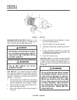
DRIVE BELT TENSIONING -- This compressor pack-
age has an automatic drive belt tensioning system.
The belts are kept at the correct tension by the spring
(figure 7--1). In the upper end of the spring, the position
of the pin indicates the correct tension on the belts. The
pin should be free in the long groove in the body of the
spring. The belts are adjusted at the factory so that the
position of the pins is at the top edge of the groove.
When the pin touches the bottom edge of the groove,
the belts are worn out and need to be replaced.
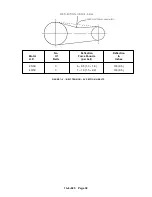
Sheaves should align straight across the front with a
straight edge.
REPLACING THE COMPRESSOR BELTS -- Use the
following instructions when replacing the drive belts:
1.
Be certain the unit is off.
2.
Disconnect, tag and lockout the power supply to
the starter.
3.
Move the belt change handle (FIGURE 7--1) to
the bottom position.
Be careful when moving the belt
change handle to the bottom posi-
tion, the belt change handle is under
spring tension.
4.
Remove the old belts and install the new belts.
5.
Lift the handle up into the top position. When the
handle is in the top position, the new belts are au-
tomatically at the correct tension.
The spring tension is adjusted to the
correct value at the factory. Do not
change the tightness by turning the
adjusting nut.
REPLACING THE COMPRESSOR OR MOTOR
SHEAVE
1.
Be certain the unit is off and that no air pressure
is in the air/oil reservoir. The compressor package
will automatically blowdown in about 2 minutes.
FIGURE 7--1 -- DRIVE BELT TENSIONER
2.
Close the air service valve located after the com-
pressor package discharge.
3.
Disconnect, tag and lockout the power supply to
the starter.
4.
Remove the screws holding the sheave to the
package and screw them into the jackbolt holes.
5.
Tighten the screws evenly until the drive bushing
and sheave are loose. They can be removed from
the shaft by hand when loosened.
6.
When installing new sheaves and bushings, re-
move all protective grease from the bushing and
sheave. install the bushing into the sheave and
align the holes.
7.
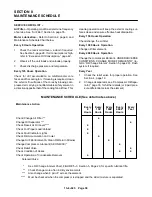
Grease the mounting screws and lightly tighten
them. The position of the mounting screws are
shown in FIGURE 7--3, page 37. The threads are
in the sheave only.
8.
Clean the shaft and mount the sheave assembly.
When mounting the sheave assembly, the bush-
ing clamps to the shaft first, the sheave can still be
Содержание EFD-25 HP
Страница 13: ...13 8 616 Page 4 DECALS 206EAQ077 212EAQ077 218EAQ077 211EAQ077 207EAQ077...
Страница 14: ...13 8 616 Page 5 DECALS 216EAQ077 217EAQ077 222EAQ077 221EAQ077 208EAQ077...
Страница 30: ...13 8 625 Page 21 FIGURE 4 4 COMPRESSOR RUNNING FULLY LOADED...
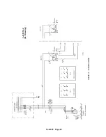
Страница 32: ...13 8 625 Page 23 FIGURE 4 5 WIRING DIAGRAM 3 305865 Ref Drawing...
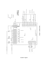
Страница 33: ...13 8 625 Page 24 FIGURE 4 6 WIRING DIAGRAM 3 305979 A Ref Drawing...
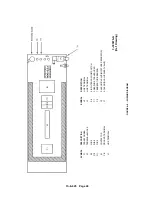
Страница 34: ...13 8 625 Page 25 FIGURE 4 7 WIRING DIAGRAM 3 305979 A Ref Drawing...
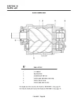
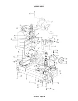
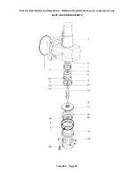
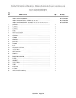
Страница 54: ...13 8 625 Page 45 AIREND GROUP...
Страница 60: ...13 8 625 Page 51 AIREND AND INLET FILTER ASSEMBLY...
Страница 62: ...13 8 625 Page 53 DRIVE GROUPS For list of Common Parts see page 54 For Drive Groups see pages 55 through 62...
Страница 72: ...13 8 625 Page 63 COOLING GROUP...
Страница 74: ...13 8 625 Page 65 CONTROL SYSTEM ASSEMBLY AND MOUNTING...
Страница 78: ...13 8 625 Page 69 CONTROL BOX 3 305979 A Ref Drawing...
Страница 80: ...13 8 625 Page 71 ENCLOSURE GROUP...

