13--8--625
Page 20
minimum pressure/check valve is used in the final dis-
charge line to provide a positive pressure on the cool-
ant system of the compressor even if the air service
valve is fully open to atmospheric pressure. This valve
also functions as a check valve to prevent backflow of
air from the shop air line when the unit stops, unloads
or is shutdown.
The valve incorporates a spring--loaded piston which
maintains approximately 45 psig in the air/oil reservoir.
When the air pressure on the upstream (air/oil reser-
voir) side of the valve rises above 45 psig, the spring is
overridden and the valve opens to full porting.
The valve does not require maintenance or adjustment.
If the valve fails to function, check the valve for dirt or
burrs, and if the o--rings or seals are worn. See the
Parts List for a listing of the kits available for rebuilding
or replacing the valve. Repair kits are available from
your local authorized Gardner Denver distributor.
Changing Minimum Pressure/Check Valve Seals
1.
Be sure the unit is completely off and that no air
pressure is in the oil reservoir. Close the service
valve.
2.
Disconnect, tag and lockout the power supply to
the starter.
3.
Tighten the nut down on the minimum pressure/
check valve cover.
4.
Remove the four (4) bolts holding the cover onto
the separator housing.
5.
Remove the snap ring in the cover.
6.
Remove the internals and replace the seals in the
minimum pressure/check valve.
7.
Re--assemble valve, including the snap ring.
8.
Tighten the cover down to the separator housing.
9.
Loosen the nut on top of the minimum pressure/
check valve .05 to .08 inches.
10. Run the unit and check for leaks.
Air/oil under pressure will cause
severe personal injury or death. Shut
down compressor, relieve system of
all pressure, disconnect, tag and
lockout power supply to the starter
before removing valves, caps, plugs,
fittings, bolts, and filters.
Inlet Valve (FIGURE 5--1, page 27) -- The inlet valve
restricts the inlet to control delivery and closes to un-
load the compressor.
At shutdown, the inlet valve
closes to prevent the back flow of air.
The inlet valve position is controlled by air pressure
which is controlled by the AIRPILOT ELECTRONIC
CONTROLLER, through the inlet valve solenoid.
When the discharge pressure reaches the unload pres-
sure programmed into the controller, the inlet solenoid
valve opens the connection between the back side of
the inlet valve piston and the air/oil reservoir and the in-
let valve spring closes the inlet valve plate.
When the discharge pressure reaches the load pres-
sure programmed into the controller, the inlet solenoid
valve is energized. This opens the connection between
the unit’s inlet and the back side of the inlet valve piston.
A partial vacuum is formed in the suction line, causing
the inlet valve to crack open and the compressor to
start producing compressed air.
The valve does not require maintenance or adjustment.
If the valve fails to function, check the valve for dirt or
burrs, and if the o--rings or seals are worn. See the
Parts List for a listing of the kits available for rebuilding
or replacing the valve. Repair kits are available from
your local authorized Gardner Denver distributor.
Inlet Valve Solenoid (FIGURE 4--4, page 21) -- This
valve controls the position of the inlet valve in response
to signals from the controller. When the inlet solenoid
valve is energized it opens a connection between the
unit’s inlet and the back side of the piston. The partial
vacuum on the inlet valve plate and piston cracks
opens the inlet valve, the pressure in the air/oil reser-
voir will open the inlet valve completely. When the inlet
valve solenoid is de--energized, a connection between
the back side of the inlet valve piston and the air/oil res-
ervoir is opened and the inlet valve spring closes the in-
let valve plate.
Blowdown Valve (FIGURE 4--4, page 21) -- This valve
is normally used for control functions, but also serves
to relieve air/oil reservoir pressure following a shut-
down.
The blowdown valve a pneumatic operated
valve that blows down the system whenever the inlet
valve solenoid closes the inlet valve and whenever the
machine is shutdown.
Purge Valve (FIGURE 4--4, page 21) -- This valve is a
pneumatic valve that lets purge air from the final dis-
charge into the inlet of the compressor. This is done to
counteract the oil knock that occurs in oil--flooded
rotary screw compressors when they are running com-
pletely unloaded with pressure in the air/oil reservoir.
This valve opens whenever the inlet valve solenoid
closes the inlet valve and opens the blowdown valve.
Содержание EFD-25 HP
Страница 13: ...13 8 616 Page 4 DECALS 206EAQ077 212EAQ077 218EAQ077 211EAQ077 207EAQ077...
Страница 14: ...13 8 616 Page 5 DECALS 216EAQ077 217EAQ077 222EAQ077 221EAQ077 208EAQ077...
Страница 30: ...13 8 625 Page 21 FIGURE 4 4 COMPRESSOR RUNNING FULLY LOADED...
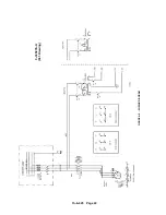
Страница 32: ...13 8 625 Page 23 FIGURE 4 5 WIRING DIAGRAM 3 305865 Ref Drawing...
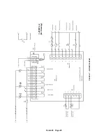
Страница 33: ...13 8 625 Page 24 FIGURE 4 6 WIRING DIAGRAM 3 305979 A Ref Drawing...
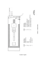
Страница 34: ...13 8 625 Page 25 FIGURE 4 7 WIRING DIAGRAM 3 305979 A Ref Drawing...
Страница 54: ...13 8 625 Page 45 AIREND GROUP...
Страница 60: ...13 8 625 Page 51 AIREND AND INLET FILTER ASSEMBLY...
Страница 62: ...13 8 625 Page 53 DRIVE GROUPS For list of Common Parts see page 54 For Drive Groups see pages 55 through 62...
Страница 72: ...13 8 625 Page 63 COOLING GROUP...
Страница 74: ...13 8 625 Page 65 CONTROL SYSTEM ASSEMBLY AND MOUNTING...
Страница 78: ...13 8 625 Page 69 CONTROL BOX 3 305979 A Ref Drawing...
Страница 80: ...13 8 625 Page 71 ENCLOSURE GROUP...


