13--8--625
Page 15
2.
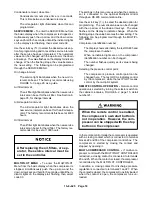
To restart the compressor, wait one (1) minute,
then turn the Emergency Stop button clockwise to
release it. Then, start the compressor per the
above instructions. In case of alarm, press the
Reset button before restarting.
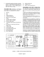
INSTRUMENT PANEL (FIGURE 4--2) -- The following
is a description of the various displays, buttons and in-
dicator lights on the Airpilot Electronic controller:
1.
Scrolling
2.
Start
3.
Stop
4.
Change Setting (up)
5.
Change Setting (down)
6.
Reset (return to basic display)
7.
Display
8.
Left upper segment of display
9.
left lower segment of display
10.
Pressure indicator light
11.
Temperature indicator light (running temp/dew
point)
12.
Operating hour indicator light (total hours/
loaded hours)
13.
Change oil light
14.
Air filter indicator light
15.
Air/oil separator indicator light
16.
Oil filter indicator light
17.
Motor indicator light
18.
Power indicator light
19.
Display indicator light
20.
Emergency stop
21.
Remote control selecting switch
PROGRAMMING AND SETUP INSTRUCTIONS
FOR THE AIRPILOT ELECTRONIC CONTROLLER
THE AIRPILOT ELECTRONIC CONTROLLER has
five menus, four of which can be accessed by the oper-
ator.
The fifth menu contains the factory settings of the com-
pressor. Access to the factory settings menu requires
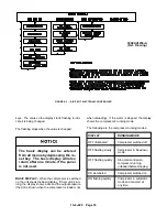
a special code. See FIGURE 4--3, page 16, for a dia-
gram of how the menus are setup.
The basic display menu shows the compressor’s run-
ning mode and information on the compressor’s vari-
ous functions.
The other menus are for programming. Programming
and setup is accomplished with the program keys, see
FIGURE 4--2. The programming menus are accessed
by simultaneously depressing the up arrow and the
down arrow keys and holding for 5 seconds. All indica-
tor lights will light up and the display will start flashing.
The 3 different menus can then be chosen using the up
arrow key. The up arrow key and the down arrow key
will increase or decrease displayed numeric values,
step through the top level menus or if pushed simulta-
neously will enable the user to go into the program
mode. The top level menus 01 for the user menu, 02
for the service menu and 03 for the multipilot menu.
The scroll (
) key will enable the user to go through
the various menu options, to change the numeric value
on the display, use the up arrow or the down arrow
FIGURE 4--2 -- STARTER / CONTROL BOX AND INSTRUMENT PANEL
Содержание EFD-25 HP
Страница 13: ...13 8 616 Page 4 DECALS 206EAQ077 212EAQ077 218EAQ077 211EAQ077 207EAQ077...
Страница 14: ...13 8 616 Page 5 DECALS 216EAQ077 217EAQ077 222EAQ077 221EAQ077 208EAQ077...
Страница 30: ...13 8 625 Page 21 FIGURE 4 4 COMPRESSOR RUNNING FULLY LOADED...
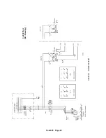
Страница 32: ...13 8 625 Page 23 FIGURE 4 5 WIRING DIAGRAM 3 305865 Ref Drawing...
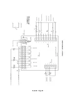
Страница 33: ...13 8 625 Page 24 FIGURE 4 6 WIRING DIAGRAM 3 305979 A Ref Drawing...
Страница 34: ...13 8 625 Page 25 FIGURE 4 7 WIRING DIAGRAM 3 305979 A Ref Drawing...
Страница 54: ...13 8 625 Page 45 AIREND GROUP...
Страница 60: ...13 8 625 Page 51 AIREND AND INLET FILTER ASSEMBLY...
Страница 62: ...13 8 625 Page 53 DRIVE GROUPS For list of Common Parts see page 54 For Drive Groups see pages 55 through 62...
Страница 72: ...13 8 625 Page 63 COOLING GROUP...
Страница 74: ...13 8 625 Page 65 CONTROL SYSTEM ASSEMBLY AND MOUNTING...
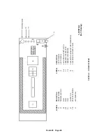
Страница 78: ...13 8 625 Page 69 CONTROL BOX 3 305979 A Ref Drawing...
Страница 80: ...13 8 625 Page 71 ENCLOSURE GROUP...


