


13--8--625
Page 8
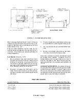
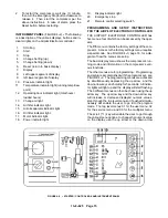
FIGURE 2--5 -- COLD WEATHER INSTALLATION
Refer to Engineering Data Sheet 13--9--411 for the ad-
vantages of using the heat recovered from rotary com-
pressors. This heat recovery could easily pay for an ad-
equate shelter for the unit.
When an outside installation must be made, the pre-
cautions required will depend on the severity of the en-
vironment. The following are general guidelines for
outside installations:
Cold Weather (Down To +10
o
F)
1.
Be sure all drains, traps, and control lines, includ-
ing pressure transducer lines are heated to avoid
freezing of condensate. Heat tape with thermo-
stat control is generally satisfactory for this pur-
pose and can be obtained at various local plumb-
ing or hardware outlets at nominal cost.
2.
Provisions to bypass the aftercooler must be
made. Since cold air contains very little moisture,
successful operation can be achieved without the
aftercooler.
3.
Provide at least some simple shelter such as a ply-
wood windbreak to protect against drifting snow.
4.
Use only Gardner Denver AEON 9000SP lubri-
cant.
5.
Monitor unit carefully during start--up and opera-
tion to be sure it is functioning normally.
Remember unsheltered (outside) installations should
be avoided where possible.
Installation next to a
heated building where enough heat can be used to
keep the compressor room above freezing will save
many complications in the operation and installation of
the unit.
AUXILIARY AIR RECEIVER -- An auxiliary air receiver
is not required if the piping system is large and provides
sufficient storage capacity to prevent rapid cycling.
When used, an air receiver should be of adequate size,
provided with a relief valve of proper setting, a pressure
gauge and a means of draining condensate.
INLET LINE LENGTHS
Length of Inlet Line
Diameter of Pipe Size
0 to 10 Feet
Same as Compressor Inlet Opening
. . . . . . . . . . . . . . . . . . . . . . . . . . . . . . . . . . . . . . . . . . . . . . . . . . . .
10 to 17 Feet
One Size Larger Than Inlet Opening
. . . . . . . . . . . . . . . . . . . . . . . . . . . . . . . . . . . . . . . . . . . . . . . . . . .
17 to 38 Feet
Two Sizes Larger Than Inlet Opening
. . . . . . . . . . . . . . . . . . . . . . . . . . . . . . . . . . . . . . . . . . . . . . . . . .
Содержание EFD-25 HP
Страница 13: ...13 8 616 Page 4 DECALS 206EAQ077 212EAQ077 218EAQ077 211EAQ077 207EAQ077...
Страница 14: ...13 8 616 Page 5 DECALS 216EAQ077 217EAQ077 222EAQ077 221EAQ077 208EAQ077...
Страница 30: ...13 8 625 Page 21 FIGURE 4 4 COMPRESSOR RUNNING FULLY LOADED...
Страница 32: ...13 8 625 Page 23 FIGURE 4 5 WIRING DIAGRAM 3 305865 Ref Drawing...
Страница 33: ...13 8 625 Page 24 FIGURE 4 6 WIRING DIAGRAM 3 305979 A Ref Drawing...
Страница 34: ...13 8 625 Page 25 FIGURE 4 7 WIRING DIAGRAM 3 305979 A Ref Drawing...
Страница 54: ...13 8 625 Page 45 AIREND GROUP...
Страница 60: ...13 8 625 Page 51 AIREND AND INLET FILTER ASSEMBLY...
Страница 62: ...13 8 625 Page 53 DRIVE GROUPS For list of Common Parts see page 54 For Drive Groups see pages 55 through 62...
Страница 72: ...13 8 625 Page 63 COOLING GROUP...
Страница 74: ...13 8 625 Page 65 CONTROL SYSTEM ASSEMBLY AND MOUNTING...
Страница 78: ...13 8 625 Page 69 CONTROL BOX 3 305979 A Ref Drawing...
Страница 80: ...13 8 625 Page 71 ENCLOSURE GROUP...


